Radar system and control method for use in a moving vehicle

a technology for moving vehicles and radar systems, applied in the direction of reradiation, measurement devices, instruments, etc., can solve the problems of large space requirements, high cost, and high complexity

Active Publication Date: 2021-06-29
GM GLOBAL TECH OPERATIONS LLC
View PDF25 Cites 2 Cited by
  • Summary
  • Abstract
  • Description
  • Claims
  • Application Information

AI Technical Summary

Benefits of technology

[0020]In another exemplary embodiment of the control method, the vehicle may include an automated driving system operably connected to the radar system. The automated driving system may be structured to autonomously control the vehicle. The control method may further include transmitting the optimal velocity hypothesis to the automated driving system. The automated driving system may be structured to control operation of the vehicle based on the optimal velocity hypothesis.
[0021]In another exemplary embodiment of the control method, the vehicle may include an automated driving system operably connected to the radar system. The automated driving system may be structured to autonomously control the vehicle. The control method may further include transmitting the elevation angle to the automated driving system. The automated driving system may be structured to control operation of the vehicle

Problems solved by technology

However, populating a wide antenna aperture with a large number of antenna elements results in high cost, high complexity, large space requirements, and high power consumption of

Method used


Image

  • Radar system and control method for use in a moving vehicle
  • Radar system and control method for use in a moving vehicle
  • Radar system and control method for use in a moving vehicle

Examples


Embodiment Construction

[0045]The following description is merely exemplary in nature and is not intended to limit the present disclosure, its application or uses. It should be understood that throughout the drawings, corresponding reference numerals indicate like or corresponding parts and features. As used herein, the term module refers to processing circuitry that may include an application specific integrated circuit (ASIC), an electronic circuit, a processor (shared, dedicated, or group) and memory that executes one or more software or firmware programs, a combinational logic circuit, and / or other suitable components that provide the described functionality.

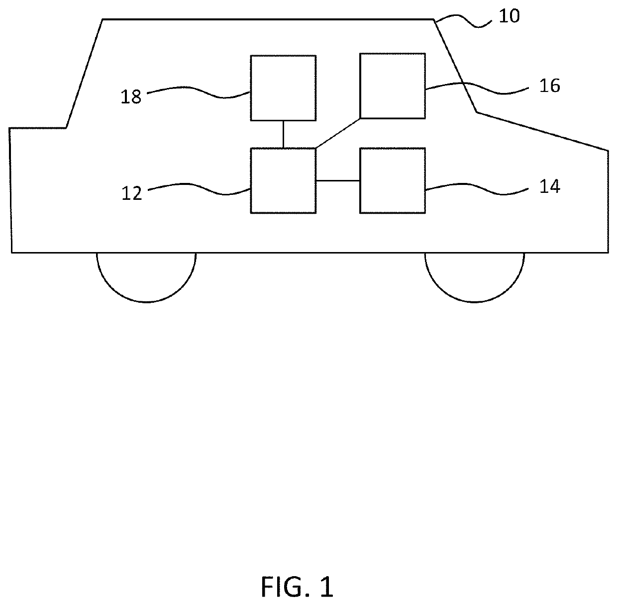
[0046]FIG. 1 illustrates an exemplary embodiment of a vehicle 10 including an automated driving system 12 and radar system 14. Automated driving system 12 may be operably connected to radar system 14, and may also include or be operably connected to additional sensors 16 configured to detect a driving environment. Sensors 16 may include a camera, a...


PUM


Abstract

A radar system for use in a vehicle moving in a first direction may include a plurality of antenna elements spaced apart in a second direction; and a controller operably connected to the plurality of antenna elements. The controller may be configured record signals received by each antenna element at each time instant of a plurality of time instants; calculate a position in the first direction of each antenna element for each time instant based on a velocity hypothesis; calculate a virtual two-dimensional antenna array response based on the signal received by each antenna element at each time instant and the position in the first direction of each antenna element at each time instant; calculate a beamforming spectrum based on the virtual two-dimensional antenna array response; and identify a peak in the beamforming spectrum to identify an elevation angle from the vehicle to a target relative to the first direction.

Description

INTRODUCTION[0001]The subject disclosure relates to a radar system and a control method for a radar system.[0002]One aspect of a radar system is detecting an angle of arrival of a signal reflected from a detection target. A wide antenna aperture allows for detection of the arrival angle with high resolution. However, populating a wide antenna aperture with a large number of antenna elements results in high cost, high complexity, large space requirements, and high power consumption of the radar system. At the same time, populating a wide antenna aperture with a small number of antenna elements results in a high level of ambiguity in the detected angle of arrival.[0003]Accordingly, it may be desirable to provide a radar system and control method that provides a wide antenna aperture for high resolution and that reduces ambiguity while reducing a total number of antenna elements to minimize complexity, cost, and power consumption.SUMMARY[0004]In one exemplary embodiment, a radar system...

Claims


Application Information

Patent Timeline
IPC IPC(8): G01S13/58G01S13/931G01S13/02G01S13/42
CPCG01S13/58G01S13/931G01S13/424G01S2013/0245G01S13/42
Inventor BIALER, ODEDJONAS, AMNON
Owner GM GLOBAL TECH OPERATIONS LLC
Why Eureka
Try Eureka