
Slip ring unit with cooling fan insulating segment

Active Publication Date: 2021-06-22
FLENDER GMBH
View PDF17 Cites 0 Cited by
  • Summary
  • Abstract
  • Description
  • Claims
  • Application Information

AI Technical Summary

Benefits of technology

The patent describes a way to cool down electrical machines using a simple insulating segment with shaped sections. These sections act like a fan to distribute cooling air to the parts of the machine. This helps to reduce the temperature of the machine and allows for better performance and higher power levels. The cooling effect can be achieved in both new and retrofitted machines. Overall, this patent provides a simple solution to a significant problem in electrical machine cooling.

Problems solved by technology

Because of this, without further measures, the temperature of the individual components of a slip ring unit would increase to a critical value, and damage to the slip ring and to the slip ring brush could occur.

Method used


Image

  • Slip ring unit with cooling fan insulating segment
  • Slip ring unit with cooling fan insulating segment

Examples


Embodiment Construction

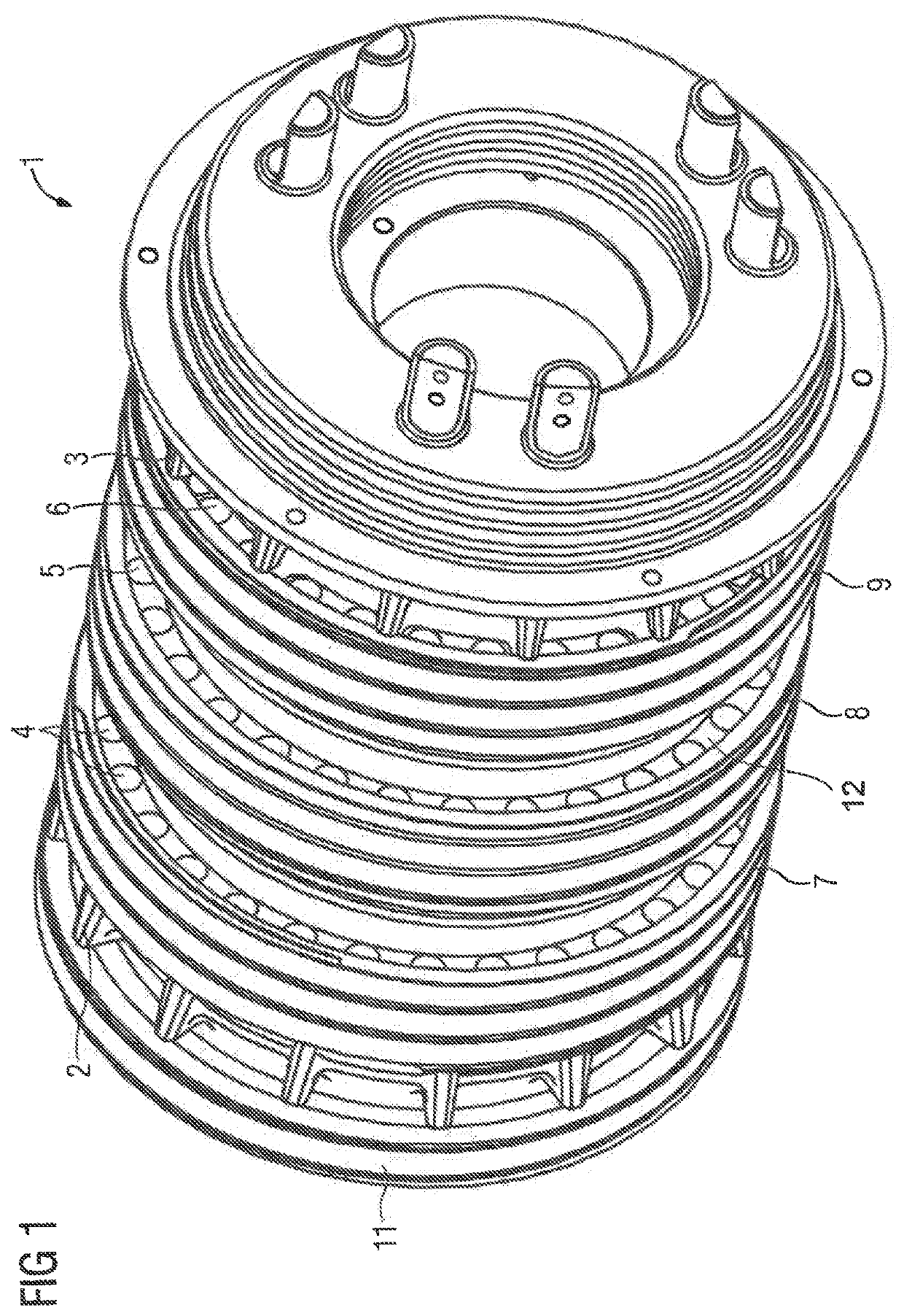
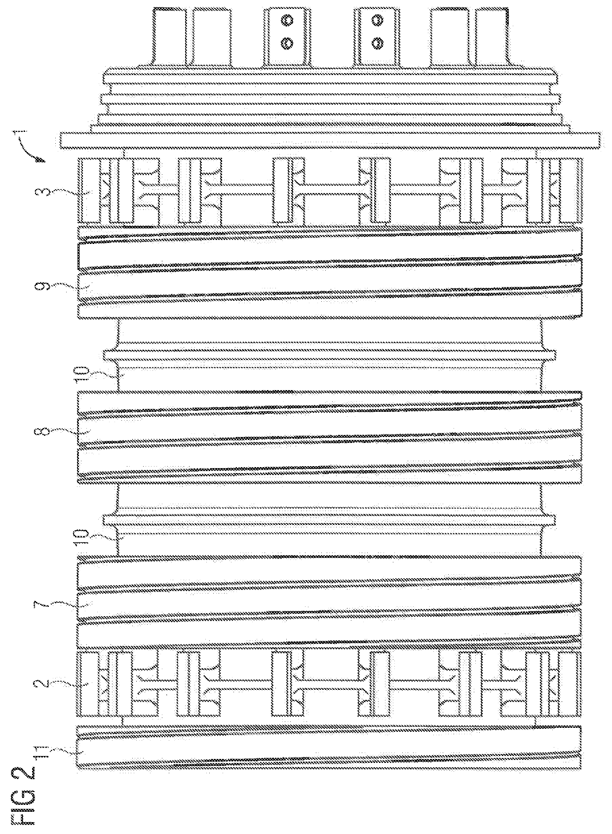
[0021]FIG. 1 shows an exemplary embodiment of a slip ring unit 1 with twin flow cooling comprising fan insulating segments 2,3 lying on the outside in each case. The slip ring body 1 depicted in FIG. 1 substantially consists of the slip rings 7,8,9, i.e. of a three-phase slip ring system as well as a grounding ring 11. Arranged between the slip rings 7,8,9 are insulating segments 2,3. The insulating segments 2,3,10 of the slip ring body 1 lying on the outside in each case have shaped sections for cooling parts of the electrical machine. The insulating segments 2,3 thus each form a type of fan unit, which are provided for the distribution of a cooling air flow to the parts of the electrical machine to be cooled. Fresh air from the surrounding environment can be directed to individual components of the electrical machine in a targeted manner as a result. To this end, the slip ring unit has slip ring boreholes 4,5,6 on the sides of supports 12 of the slip rings 7,8,9. Said slip ring bo...


PUM


Abstract

A slip ring unit for an electrical machine is provided for accommodating a carbon brush system. The slip ring unit includes at least one insulating segment having shaped sections for cooling parts of the electrical machine. The insulating segment having the shaped sections is shaped from the insulating segment as a fanwheel, wherein the insulating segment having the shaped sections forms a fan to distribute a cooling air flow to the parts of the electrical machine to be cooled. The slip ring unit has boreholes on the sides of supports of the slip rings for passage of cooling air.

Description

CROSS-REFERENCES TO RELATED APPLICATIONS[0001]This application is the U.S. National Stage of International Application No. PCT / EP2017 / 076537, filed Oct. 18, 2017, which designated the United States and has been published as International Publication No. WO 2018 / 091215 and which claims the priority of European Patent Application, Serial No, 16198783.9, filed Nov. 15, 2016, pursuant to 35 U.S.C. 119(a)-(d).BACKGROUND OF THE INVENTION[0002]The invention relates to a slip ring unit for an electrical machine, wherein the slip ring unit is provided for accommodating a carbon brush system and wherein the slip ring unit has at least one insulating segment.[0003]The invention furthermore relates to an electrical machine with a slip ring unit of this kind.[0004]A slip ring unit of this kind for an electrical machine is used in wind turbines, for example. Here, it is necessary for the electrical machines in the form of the generators and their components to become more and more compact. This l...

Claims


Application Information

Patent Timeline
IPC IPC(8): H02K9/28F03D80/60H01R39/08H01R39/26H02K7/18H02K13/00
CPCH02K9/28F03D80/60H01R39/08H01R39/26H02K7/183H02K13/003Y02E10/72
Inventor BINDER, HERBERTMEMMINGER, OLIVERRASKOPF, ANDREJSCHIFFERER, KLAUS
Owner FLENDER GMBH
Learn More