
Orbital sprinkler with speed control brake

a technology of speed control and sprinkler head, which is applied in the direction of spraying apparatus, spray nozzle, movable spraying apparatus, etc., can solve the problems of high speed of rotation of the wobbling sprinkler head, shortening the throw radius of the sprinkler, and bulky framework

Active Publication Date: 2021-06-01
NELSON IRRIGATION CORP
View PDF32 Cites 0 Cited by
  • Summary
  • Abstract
  • Description
  • Claims
  • Application Information

AI Technical Summary

Benefits of technology

The described sprinkler head provides for desired outward movement and braking without needing a large fixed frame. The head can be used with a smaller diameter canister and is flexible for different water patterns without extra cost or complexity. The head also includes a water deflector plate that creates emerging / receding streams for uniform distribution without an external diffuser. The head uses a smooth ledge instead of ridges and teeth to prevent slipping without interfering with the orbital motion of the head.

Problems solved by technology

There are potential shortcomings, however, that can nullify the very nutating affect that makes such sprinklers attractive in the first instance.
One problem often encountered with sprinklers of this type relates to stalling at start-up or even during normal operation.
Stalling occurs when the water distribution plate of the sprinkler head fails to tilt at start-up, or ceases tilting during operation, thereby simply rotating and distributing a stream particularly susceptible to the “donut effect” where the wetted pattern area is shaped like a solid ring around a dry center.
Another problem relates to the relatively high speed of rotation of the wobbling sprinkler head.
High rotational speeds create the well-known but undesirable “horse-tail” effect that shortens the radius of throw of the sprinkler.
The framework is bulky and expensive.
Moreover, the fixed strut portions of the framework create dry shadows in the water pattern.
Still further, stringy material such as moss or food processing waste in the water can hairpin and build up on the struts and cause stalling issues.
A minor drawback with this design is that as the ridges roll across the teeth of the gear plate, the wobbler cage is shifted up and down as it rolls between the flats of the ridges.
This can create unwanted drool and inconsistency in the water pattern.

Method used


Image

  • Orbital sprinkler with speed control brake
  • Orbital sprinkler with speed control brake
  • Orbital sprinkler with speed control brake

Examples


Embodiment Construction

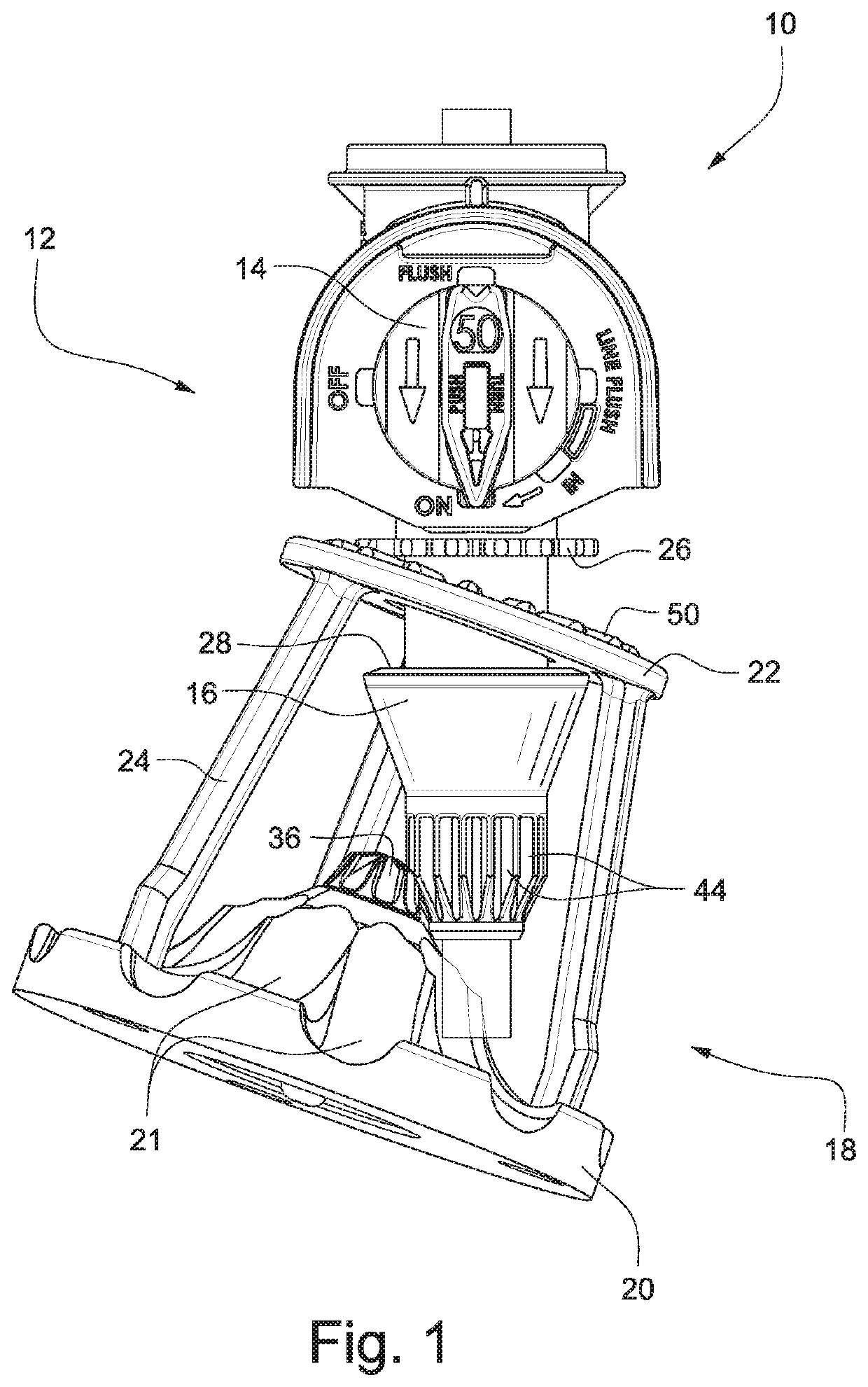
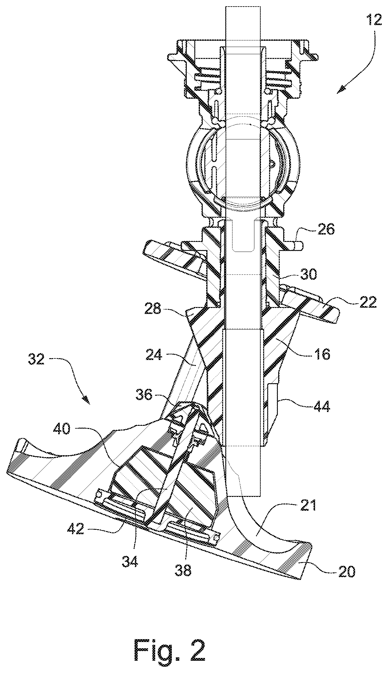
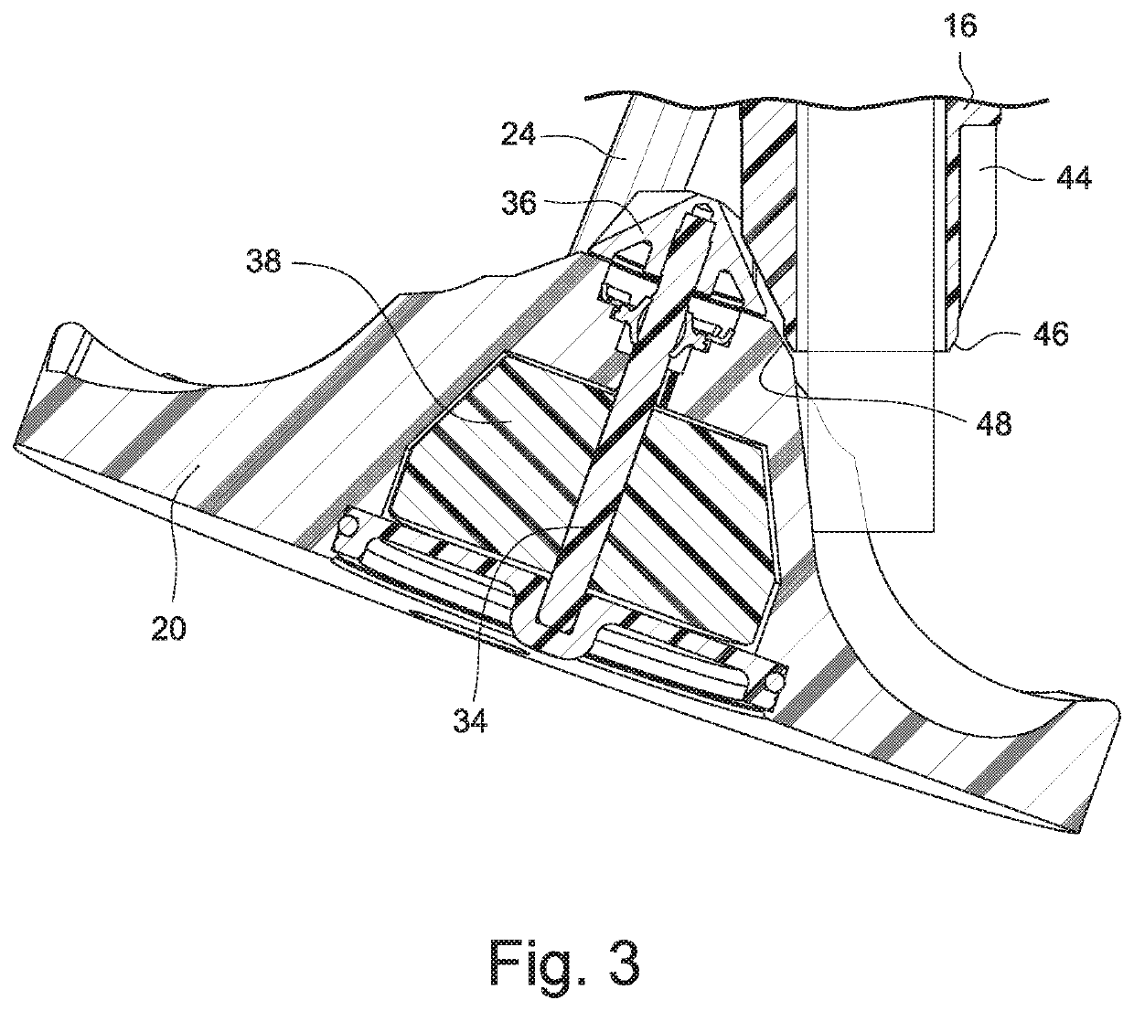
[0051]FIGS. 1-4 show a wobbler-type sprinkler head 10 according to an exemplary embodiment. The sprinkler head 10 includes a sprinkler body 12 and a nozzle 14 positioned within the sprinkler body 12. In some embodiments, the nozzle 14 is a nozzle insert that is positionable in a sideways-oriented, complementary recess provided in the sprinkler body 12. The nozzle / nozzle insert 14 may be formed as a substantially-cylindrical body, possibly injection-molded of hard plastic material such as PVC (or other suitable plastic or metal material). The nozzle 14 may be provided with a nozzle bore with an inlet in communication with water flow and an outlet or nozzle outlet orifice that nozzles or meters water output from the sprinkler body 12.

[0052]A fixed gear 16 is coupled with the sprinkler body 12, and a wobbler cage 18 is supported on the sprinkler body 12. A water deflector plate 20 is coupled with the wobbler cage 18 and disposed downstream of the nozzle 14. The water deflector plate 20...


PUM


Abstract

A spool and wobbler assembly for a sprinkler includes a spool section with facing spool flanges on opposite sides of a spool core, where at least one of the spool flanges includes a circumferential rolling ledge. A wobbler cage including a wobbler ring is supported on the spool section, and a water deflector plate is coupled with the wobbler cage. An underside of the wobbler ring is provided with a circumferential rolling surface that engages the circumferential rolling ledge of the at least one spool flange. The rolling surface and rolling ledge provide for smoother orbital motion of the deflector plate.

Description

CROSS-REFERENCES TO RELATED APPLICATIONS[0001]This application is a continuation-in-part of U.S. patent application Ser. No. 15 / 161,920, filed May 23, 2016, pending, the entire contents of which are hereby incorporated by reference in this application.STATEMENT REGARDING FEDERALLY SPONSORED RESEARCH OR DEVELOPMENT[0002](NOT APPLICABLE)BACKGROUND[0003]The invention relates to sprinkler heads and, more particularly, to sprinkler heads that nutate, or wobble, while they rotate, to thereby minimize the “donut effect” prevalent with conventional rotating sprinkler heads.[0004]Various nutating or wobbling sprinkler head designs have been proposed, examples of which are described in prior U.S. Pat. Nos. 5,381,960; 5,950,927; 6,530,532 and 6,932,279. Commonly owned U.S. Pat. Nos. 5,439,174; 5,588,595; 5,671,885; 6,267,299; 6,341,733; 6,439,477; 7,287,710; 7,395,977; 7,562,833; 7,942,345; 8,028,932 and 8,991,724 provide further examples of nutating or wobbling sprinkler heads. There are pote...

Claims


Application Information

Patent Timeline
Patent Type & Authority Patents(United States)
IPC IPC(8): B05B3/00B05B3/04B05B1/32B05B15/74
CPCB05B3/008B05B3/005B05B3/0486B05B1/323B05B15/74
Inventor SESSER, GEORGE L.NELSON, CRAIG B.HELLIE, ANDREW B.CRAWFORD, STEVEN E.
Owner NELSON IRRIGATION CORP
Learn More