
Electronic device capable of detecting wearing state or touching state

a technology of wear and touch, applied in the field of wear and touch detection devices, can solve the problems of inability to provide security mechanisms to avoid such issues, failure of biochemical information detection, etc., and achieve the effect of restricting the security mechanism

Active Publication Date: 2021-05-25
PIXART IMAGING INC
View PDF5 Cites 1 Cited by
  • Summary
  • Abstract
  • Description
  • Claims
  • Application Information

AI Technical Summary

Benefits of technology

The invention allows for detection of how an electronic device is being worn and where it is being worn from using electrodes on the device. This helps to improve the security of the device as it can detect if it is being worn improperly.

Problems solved by technology

However, the biological information detection may fail or non-accurate if the user does not wear the smart wearable electronic device in a proper manner.
However, no security mechanism is provided to avoid such issue.

Method used


Image

  • Electronic device capable of detecting wearing state or touching state
  • Electronic device capable of detecting wearing state or touching state
  • Electronic device capable of detecting wearing state or touching state

Examples


Embodiment Construction

[0017]In following descriptions, a plurality of embodiments are provided to explain the concept of the present invention. Please note the components in following embodiments can be implemented by hardware (e.g. circuit or device), or implemented by firmware (e.g. a processor installed with at least one program). Also, the components in each embodiment can be integrated to fewer components, or be divided to more components. Furthermore, the terms “first”, “second” . . . in following embodiments are only for defining different components, steps or parameters, but do not mean to limit the sequences thereof.

[0018]Additionally, in following embodiments, a smart watch is taken as an example to explain the concepts of the present invention. However, the wearable electronic device is not limited to a smart watch. Furthermore, the concept disclosed by the present invention can be applied any other kind of electronic device to detect a touch state or a wearing state of the electronic device r...


PUM

PropertyMeasurementUnit
capacitanceaaaaaaaaaa
capacitance calculatingaaaaaaaaaa
distanceaaaaaaaaaa

Abstract

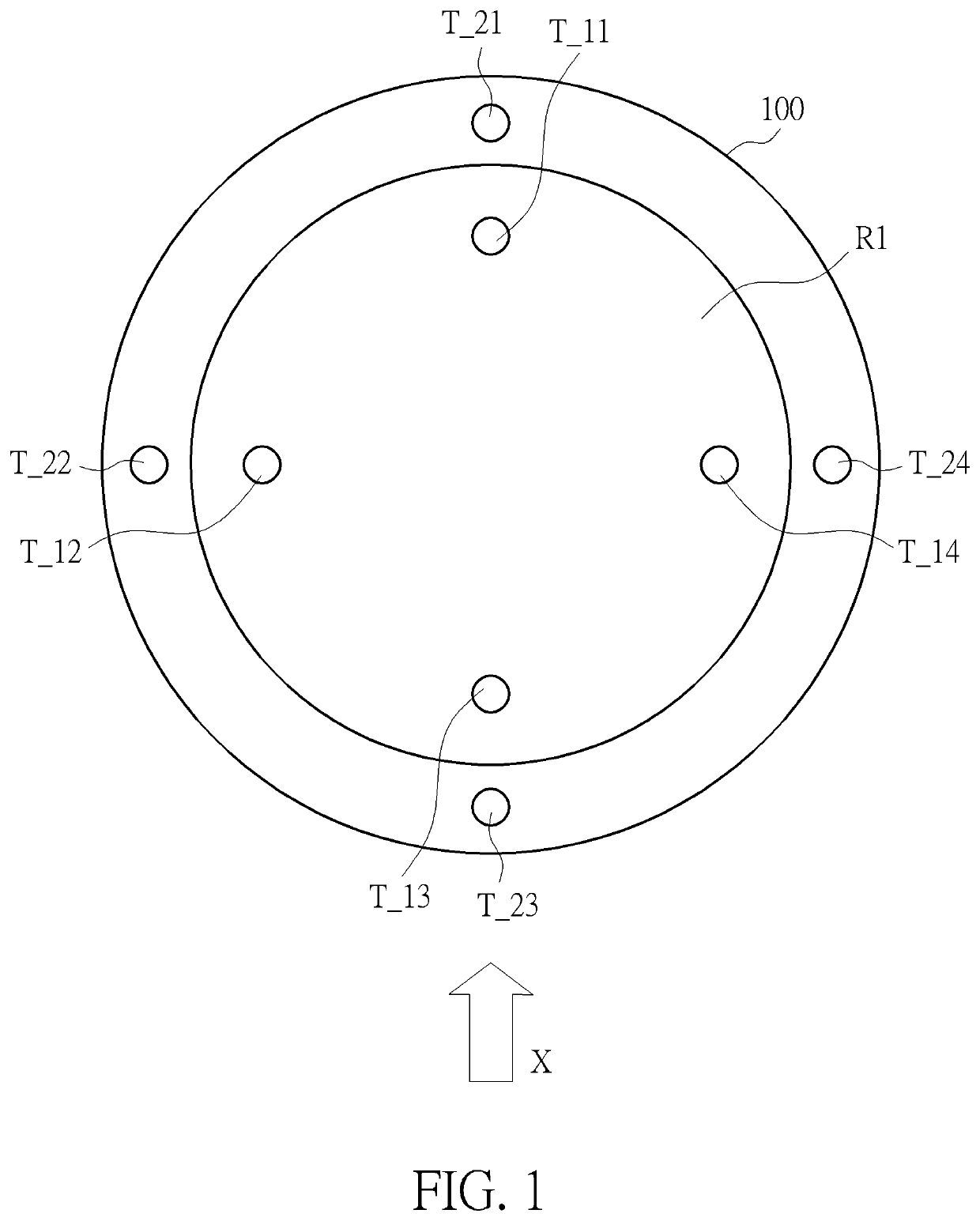
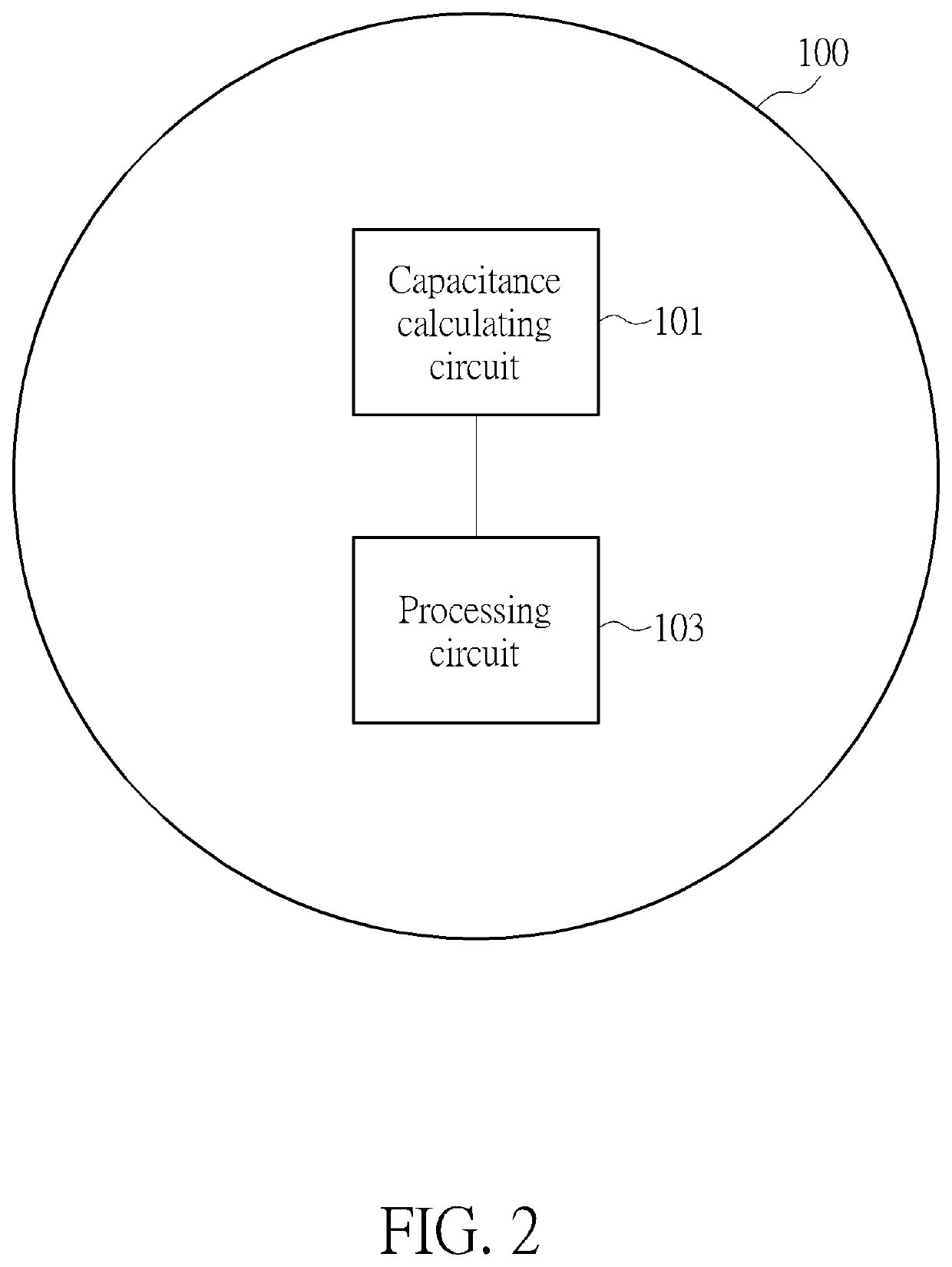
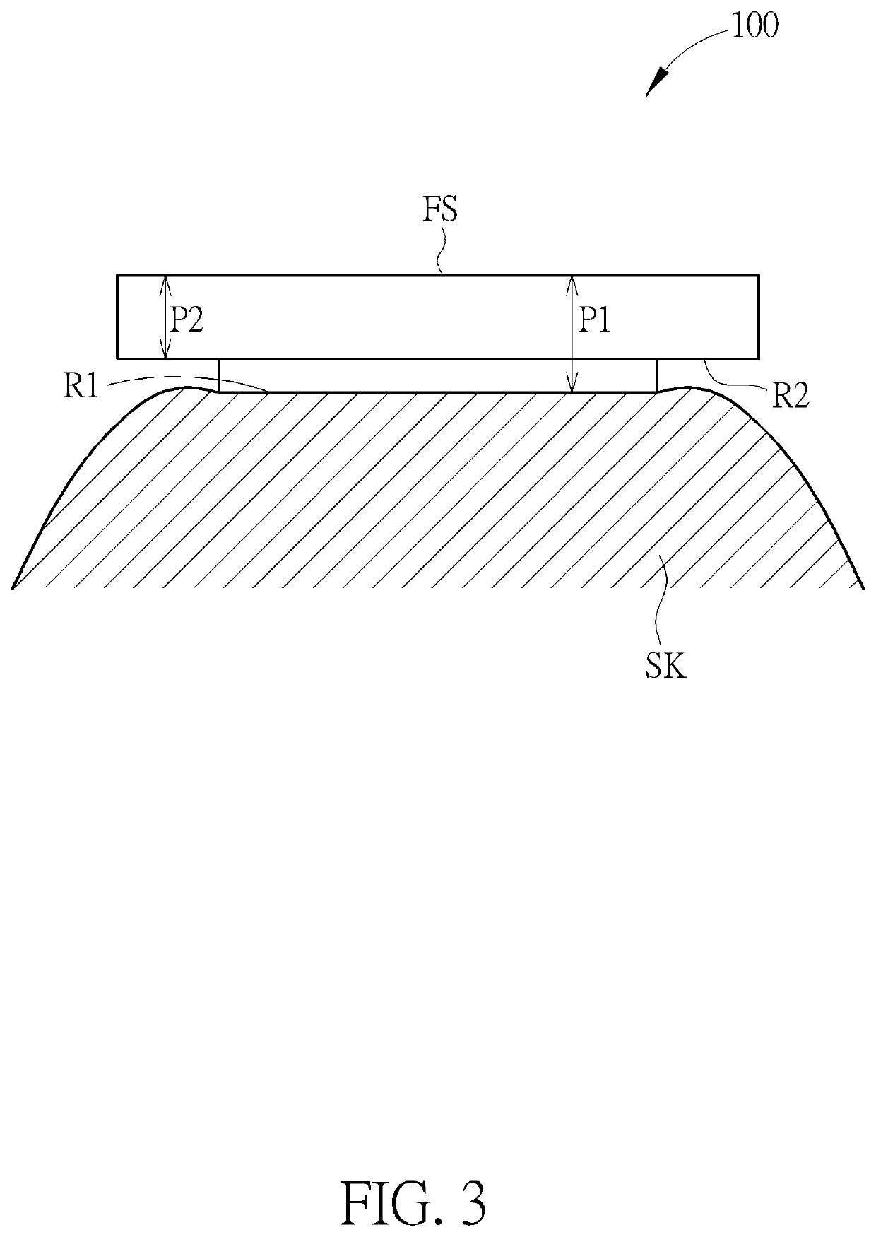
A wearable electronic device which can detect a wearing state, comprising: at least one first electrode, provided in a first region of the wearable electronic device; at least one second electrode, provided in a second region of the wearable electronic device; a capacitance calculating circuit, configured to calculate first capacitances generated by the first electrode and configured to calculate second capacitances generated by the second electrode, wherein the capacitance calculating circuit further calculates a capacitance difference between the first capacitance and the second capacitance; and a processing circuit, configured to determine the wearing state according to the capacitance difference. Via such structure, a wearing state, a wearing location, a wearing angle of the electronic device can be automatically detected, thus the problem caused by an improper wearing manner can be improved.

Description

BACKGROUND OF THE INVENTION1. Field of the Invention[0001]The present invention relates to an electronic device capable of detecting a wearing state or a touching state, and particularly relates to an electronic device having at least one electrode to detect a wearing state or a touching state.2. Description of the Prior Art[0002]In recent years, a smart wearable electronic device such as a smart watch or a smart wristband has become more and more popular. Such smart wearable electronic device always has various functions, such as mobile payment or biological information detection (e.g. heart rate). However, the biological information detection may fail or non-accurate if the user does not wear the smart wearable electronic device in a proper manner. Also, the smart wearable electronic device always needs to be recognized before using the mobile payment. If the smart wearable electronic device is stolen after being recognized, someone who steals it can use this device to pay any bil...

Claims


Application Information

Patent Timeline
Patent Type & Authority Patents(United States)
IPC IPC(8): G06F1/16G06F3/041G06F3/044
CPCG06F1/163G06F3/044G06F3/0412G06F3/0416G06F3/0304G06F1/1684G06F1/3231G04G21/025G04G21/08G06F21/316G06Q20/321G06Q20/401Y02D10/00
Inventor TSAI, MING-HUNGSU, TSE-CHUNGGU, REN-HAUSU, TZUNG-MIN
Owner PIXART IMAGING INC
Learn More