
Optical trapping of airborne particles using dual counter-propagating hollow conical beams

a technology of optical trapping and airborne particles, which is applied in the field of optical trapping and holding airborne particles, can solve the problems of difficult air trapping of airborne particles, inability to successively trap arriving transparent particles at a reasonable trapping efficiency, and many problems of airborne particles

Active Publication Date: 2021-05-25
UNITED STATES OF AMERICA THE AS REPRESENTED BY THE SEC OF THE ARMY
View PDF6 Cites 4 Cited by
  • Summary
  • Abstract
  • Description
  • Claims
  • Application Information

AI Technical Summary

Benefits of technology

The present invention is about a device, system, and method for trapping and holding airborne particles using an optical trap. The optical trap generates hollow conical beams that can trap particles in air. It can be used for both absorbing and non-absorbing particles, and can hold multiple particles simultaneously. The optical trap can also be used for particle detection and measurement, and can continuously sample particles from air. The technical effects of this invention include improved trapping and holding of airborne particles, as well as improved detection and measurement of their properties.

Problems solved by technology

Airborne particles pose many problems.
Trapping a particle in air is more difficult than trapping a particle in a liquid (or on a substrate) since the trap must overcome stronger scattering forces, gravity and air turbulence without help from the higher viscosity of a liquid.
But, experiments showed that the optical trap system was not able to successively trap arriving transparent particles at a reasonable trapping efficiency (i.e., >1%).
It was determined that the relatively weak restoring force in this optical trap cannot provide high trapping efficiency for transparent particles, especially for flowing through transparent particles with high refractive indexes (i.e., n>1.5).

Method used


Image

  • Optical trapping of airborne particles using dual counter-propagating hollow conical beams
  • Optical trapping of airborne particles using dual counter-propagating hollow conical beams
  • Optical trapping of airborne particles using dual counter-propagating hollow conical beams

Examples


Embodiment Construction

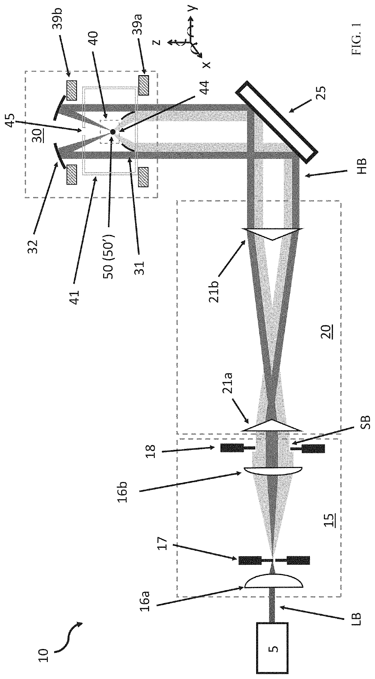
[0023]A novel optical trapping apparatus and methods for using the same are disclosed. This innovative optical trapping generates and utilizes dual counter-propagating hollow conical beams for trapping and holding particles in air. This technology has been demonstrated for trapping of both absorbing and transparent particles with either spherical or spatially irregular geometries.

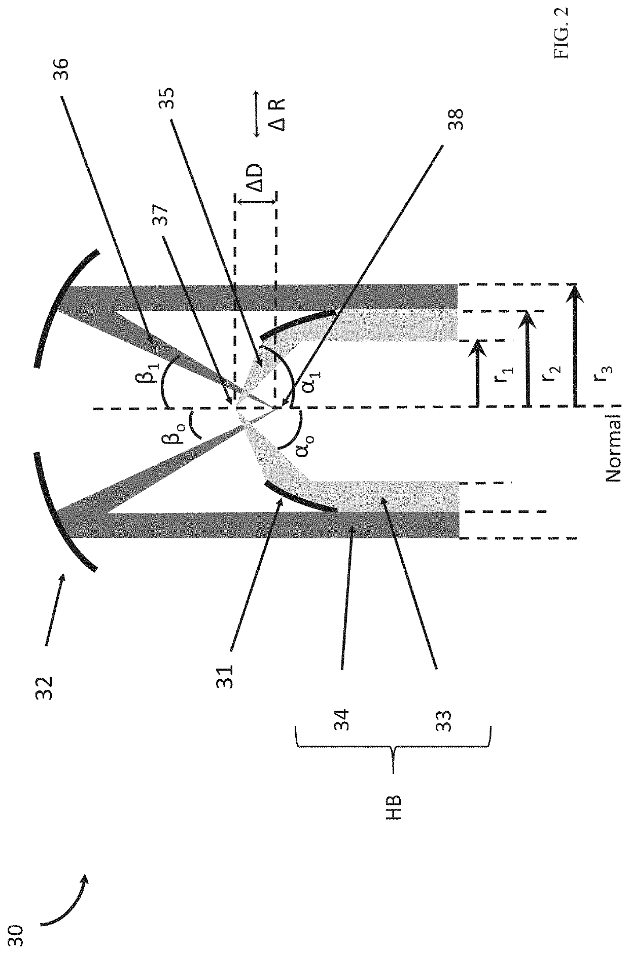
[0024]The optical trap is formed by manipulating a single light beam output from a light source. This light beam is shaped and formed into a hollow beam having a ring or ring-like geometry or profile, i.e., the center of the beam is removed where the contribution to the incident photon momentum along the optical axis is strongest. The hollow beam is then is split into two portions which are focused, using a pair of parabolic reflectors, to form the dual counter-propagating hollow conical beams. Particle trapping occurs at and / or between the focal points of the hollow conical beams.

[0025]FIG. 1 is a schemati...


PUM

PropertyMeasurementUnit
transparentaaaaaaaaaa
wavelengthaaaaaaaaaa

Abstract

Embodiments of the present invention are directed to systems and methods for trapping and holding airborne particles, for further measurement and characterization. In the various embodiments, an optical trap is provided which generates and uses dual hollow conical beams to trap and hold absorbing and non-absorbing, spherical and irregularly shaped, liquid and solid airborne particles. The optical trap may include: a light source for generating a beam of light; optics for shaping and forming a hollow conical beam having a ring geometry from the beam of light; a trapping region where a particle can be present to be trapped; a first parabolic reflector configured to focus an inner portion of the hollow conical beam to a first focal point in the trapping region; and a second parabolic reflector configured to focus an outer portion of the hollow conical beam to a second focal point in the trapping region.

Description

GOVERNMENT INTEREST[0001]The invention described herein may be manufactured, used and licensed by or for the U.S. Government without the payment of royalties thereon.BACKGROUND OF THE INVENTIONField[0002]Embodiments of the present invention are generally directed to trapping and holding airborne particles, and more particularly, to optical traps which generate and use dual counter propagating hollow conical beams for trapping and holding particles in air.Description of Related Art[0003]Airborne particles pose many problems. The ability to trap airborne particles for inspection and / or measurement is important for many applications. Conventional techniques to optically trap airborne particles use radiation pressure force, photophoretic force, or the combination. Trapping a particle in air is more difficult than trapping a particle in a liquid (or on a substrate) since the trap must overcome stronger scattering forces, gravity and air turbulence without help from the higher viscosity o...

Claims


Application Information

Patent Timeline
Patent Type & Authority Patents(United States)
IPC IPC(8): G02B21/32G01N15/14G02B17/08G02B21/26
CPCG02B21/32G01N15/1434G01N15/1484G02B17/0868G02B21/26G01N2015/1493G01N2015/1497G01N2015/1415G01N2015/1438G01N15/1436G01N15/1459G01N2015/1486G02B27/0938G01N2015/1027
Inventor PAN, YONGLEKALUME, AIMABLE
Owner UNITED STATES OF AMERICA THE AS REPRESENTED BY THE SEC OF THE ARMY
Learn More