
Sliding window assembly

a window assembly and sliding technology, applied in the direction of vehicle maintenance, wing accessories, vehicle cleaning, etc., can solve the problems of increasing assembly and system costs, reducing valuable packaging space within the vehicle, and electrical wiring and components, so as to increase the robustness, energize the heating element, and preserve the mechanical functionality of the system

Active Publication Date: 2021-05-18
AGC AUTOMOTIVE AMERICAS CO A DIV OF AGC FLAT GLASS NORTH AMERICA INC +2
View PDF38 Cites 3 Cited by
  • Summary
  • Abstract
  • Description
  • Claims
  • Application Information

AI Technical Summary

Benefits of technology

[0011]The sliding window assembly and the cable drive system advantageously provide the cable, which not only mechanically moves the sliding window between the open and closed position, but also transfers electrical current to the heating element of the sliding window. Thus, the cable serves a dual electro-mechanical purpose allowing elimination of separate and independent electrical wiring for energizing the heating element. Furthermore, the sliding window assembly and the cable drive system eliminate a need to have separate and independent devices to open and close the sliding window and to energize the heating element.
[0012]Electrical and moving interaction between the conductive element and the conductive terminal allows current to be transferred from the power supply to the heating element through moving parts, such as the drum or the cable. Electrical connection between the conductive terminal and the conductive element is maintained while preserving mechanical functionality of the system. That is, the conductive terminal and the conductive element are electrically connected in a moveable manner without being permanently fixed to one another. Movement of the cable or drum is not compromised. As such, energizing of the heating element is possible for any given position of the sliding window and the sliding window may be moved whether or not the heating element is being energized. Moreover, the sliding window assembly and cable drive system provide increased robustness, packaging space savings, and component reduction.

Problems solved by technology

Such separate electrical wiring requires additional wiring and components thereby increasing cost to the assembly and system.
Moreover, such separate electrical wiring and components reduce valuable packaging space within the vehicle.

Method used


Image

  • Sliding window assembly
  • Sliding window assembly
  • Sliding window assembly

Examples


Embodiment Construction

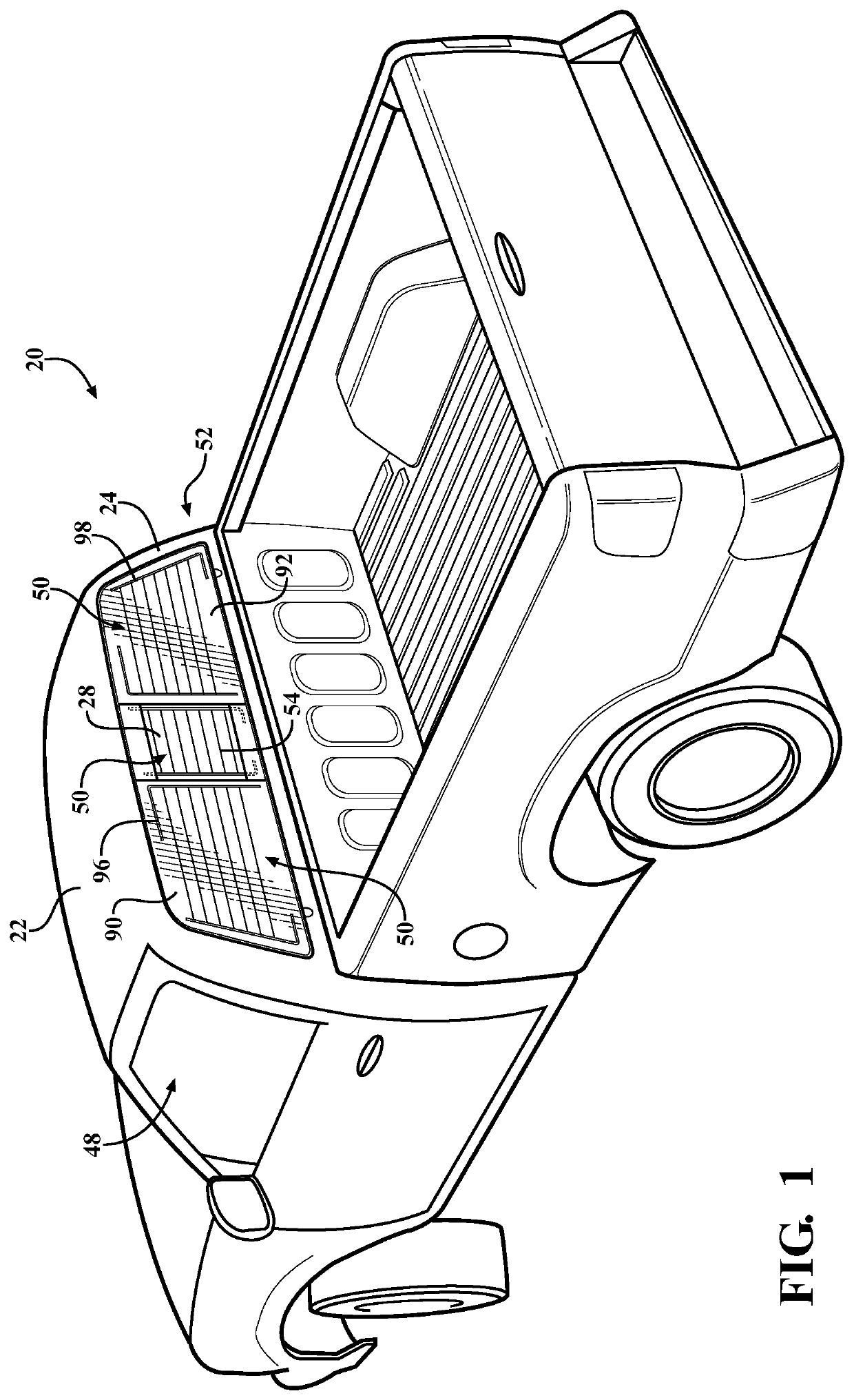
[0041]Referring to the Figures, wherein like numerals indicate like or corresponding parts throughout the several views, a sliding window assembly 20 for a vehicle 22 is generally shown. Typically, as shown in FIG. 1, the sliding window assembly 20 is coupled to a rear window body 24 of a pickup truck 22. However, it is to be appreciated that the sliding window assembly 20 can be coupled to any suitable location of other types of vehicles or non-vehicles.

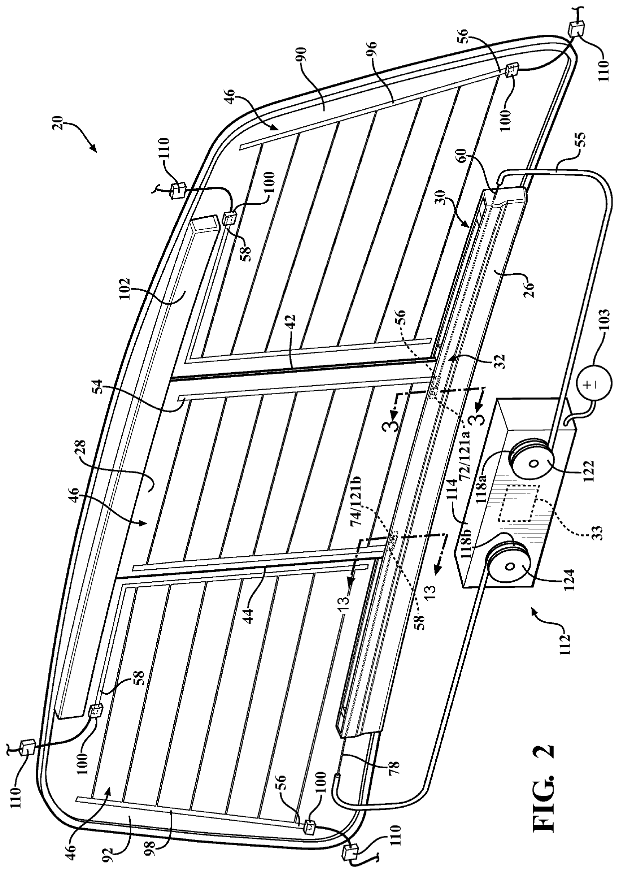
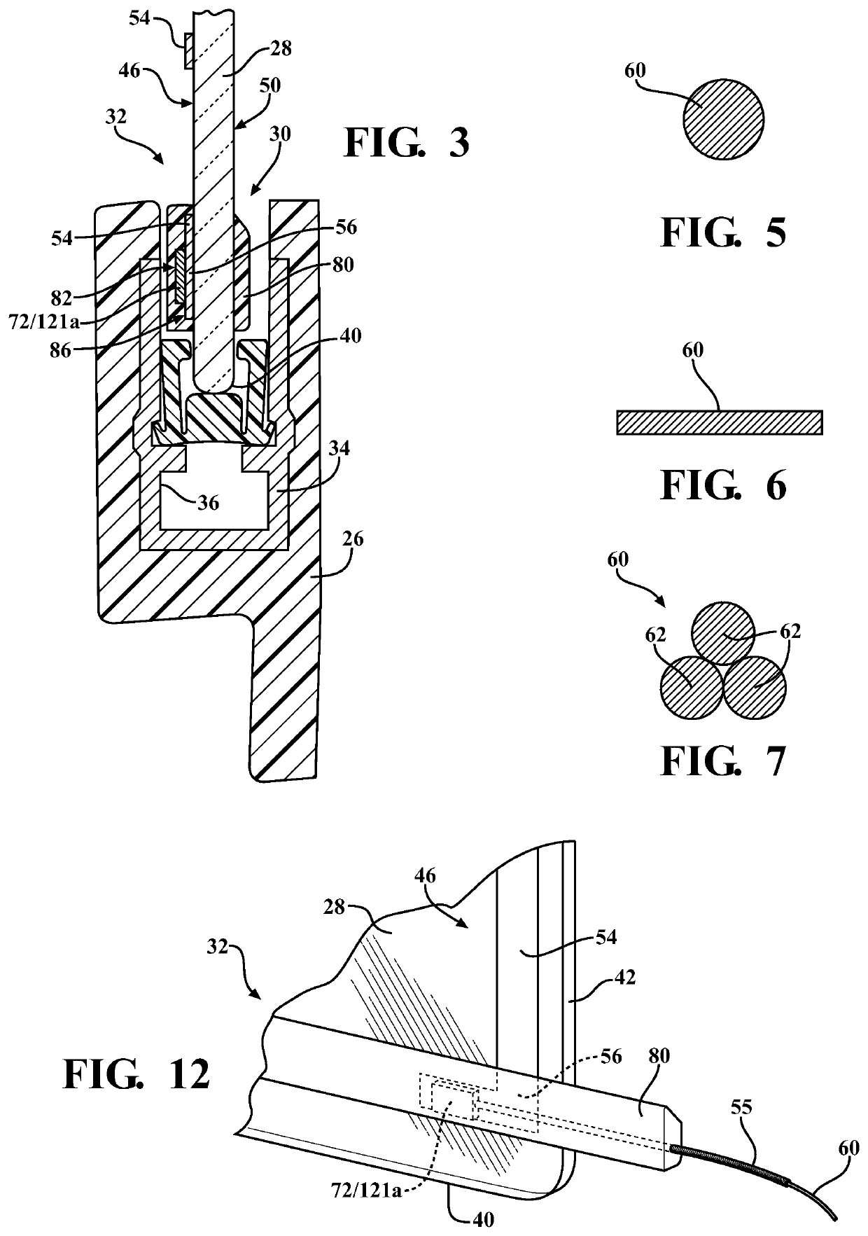
[0042]As best shown in FIGS. 2 and 3, the sliding window assembly 20 includes a guide track (hereinafter “track”) 26 adapted to be coupled to the vehicle 22 and a sliding window 28 movably coupled to the track 26. More specifically, the track 26 defines a slot 30 for receiving and guiding the sliding window 28. The sliding window 28 includes a bottom portion 32 at least partially disposed in the track 26. The sliding window 28 is movable relative to the track 26 between an open position as shown in FIG. 4 and a closed position as sh...


PUM


Abstract

A sliding window assembly, a cable drive system and methods of operating the same, are disclosed. The sliding window assembly includes a guide track and a sliding window movable relative to the guide track. A heating element is coupled to the sliding window for heating the sliding window. A drum of a drive assembly rotates and includes a conductive terminal connected to a power supply of the vehicle. A cable is coupled between the sliding window and heating element and the drum. The drum rotates to mechanically wind or unwind the cable for moving the sliding window. A conductive element is coupled to at least one of the drum and the cable and is electrically connected to the cable and is movable during movement of the sliding window. The conductive element contacts the conductive terminal to provide electrical current to the cable for energizing the heating element.

Description

CROSS-REFERENCE TO RELATED APPLICATIONS[0001]This application is the National Stage of International Patent Application No. PCT / US2015 / 052923, filed on Sep. 29, 2015, which claims priority to and all the advantages of U.S. provisional patent application No. 62 / 056,923, filed Sep. 29, 2014, the disclosure of which is hereby incorporated by reference in its entirety.BACKGROUND OF THE INVENTION[0002]1. Field of the Invention[0003]The subject invention generally relates to a sliding window assembly and a cable drive system and for a vehicle.[0004]2. Description of the Related Art[0005]Window assemblies for vehicles are known in the art. One type of window assembly includes a first panel and a second panel each fixed to the vehicle. The first and second panels are spaced from each other to define an opening therebetween. A sliding window is disposed between the first and second panels and is movable relative to the first and second panels between an open position and a closed position to...

Claims


Application Information

Patent Timeline
Patent Type & Authority Patents(United States)
IPC IPC(8): H05B3/84B60J1/18E05F15/643E05F11/53E05F15/60B60S1/02E05D15/06
CPCH05B3/84B60J1/1853B60S1/026E05D15/06E05F11/535E05F15/60E05F15/643E05Y2900/55H05B2203/005H05B2203/014H05B2203/016
Inventor LAHNALA, DAVID W.BENNETT, DANIELBACH, JAMES W.
Owner AGC AUTOMOTIVE AMERICAS CO A DIV OF AGC FLAT GLASS NORTH AMERICA INC
Learn More