Steerable extendable devices
a technology of extendable devices and steering devices, which is applied in the field of medical devices, robotics, oil and gas, civil engineering, disaster robotics, etc., can solve the problems of multiple punctures or incisions, time-consuming, and inability to access the target region of current devices, so as to avoid iterative, time-consuming, and potentially traumatic manipulation
- Summary
- Abstract
- Description
- Claims
- Application Information
AI Technical Summary
Benefits of technology
Problems solved by technology
Method used
Image

Examples
1st embodiment
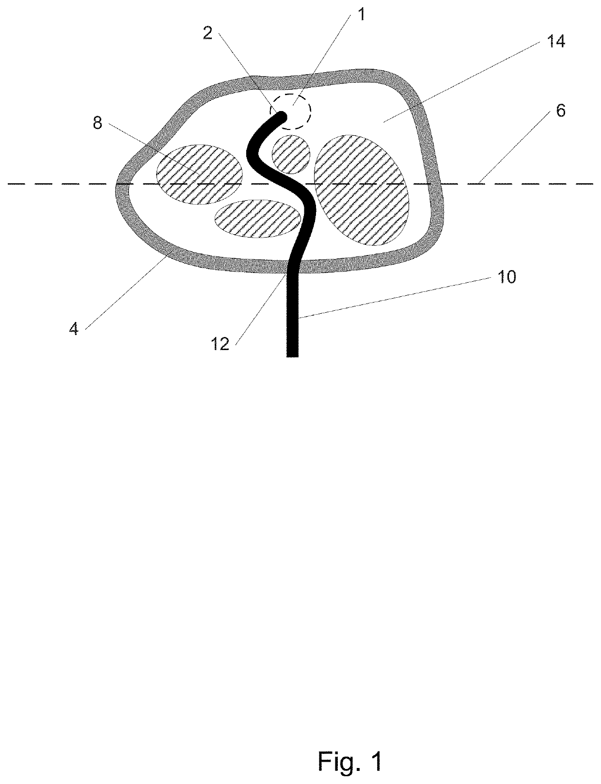
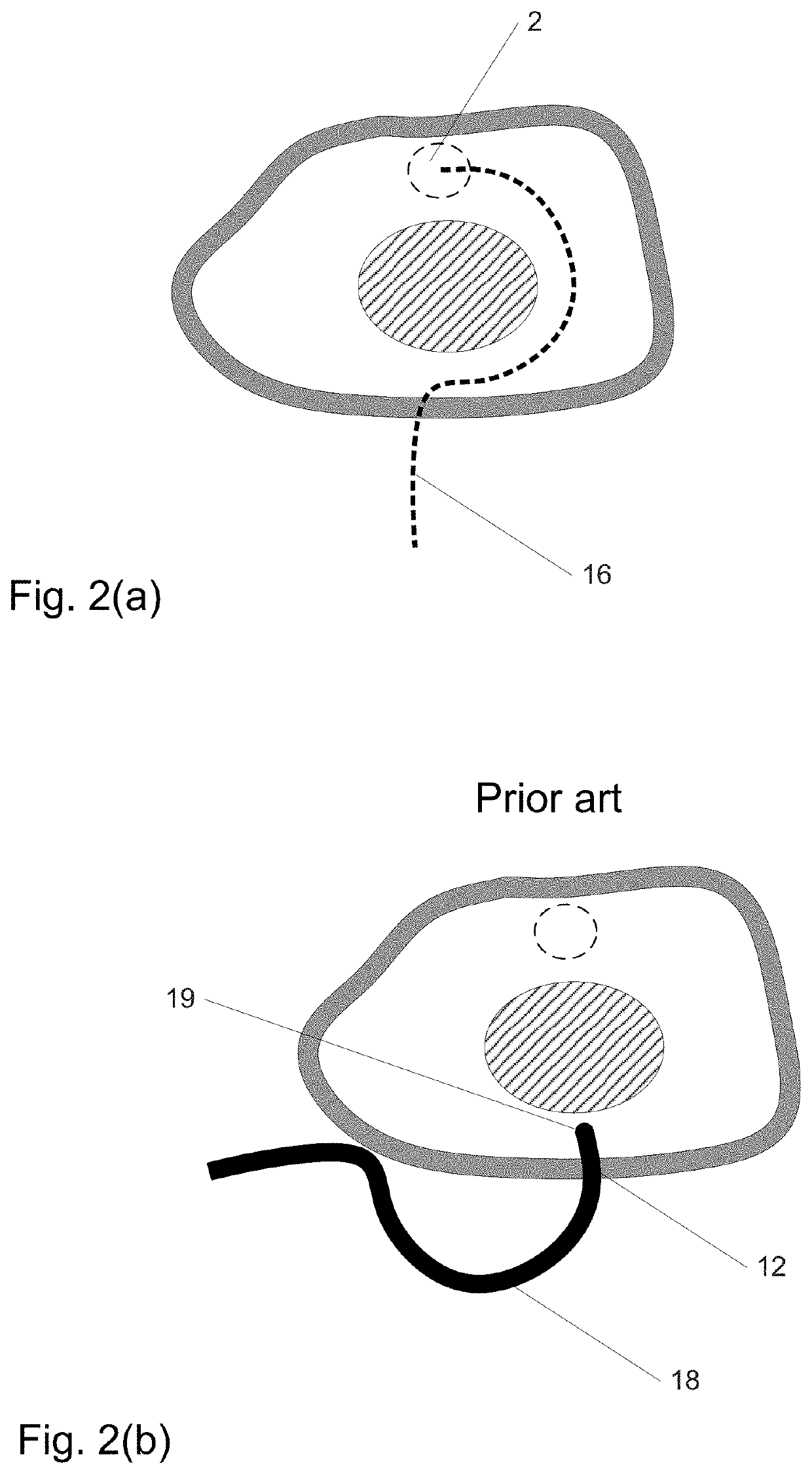
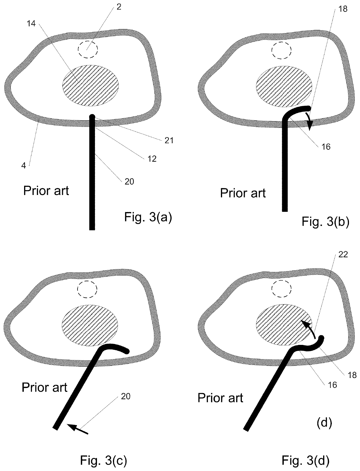
[0113]In a 1st embodiment of the invention, an instrument enters the body and is delivered along a desired path such as path 16 of FIG. 2(a) as illustrated in FIGS. 4(a-c) to reach region 2. The path may be determined, for example, using imaging such as CT or MM. In FIG. 4(a), instrument 30 enters the skin 4 through puncture site 12 and begins to follow path 16, curving as it grows or elongates with its distal end 32 in the lead. In FIG. 4(b), the instrument has lengthened further and in FIG. 4(c) distal end 32 has reached region 2 as desired. Such a “distal growth” behavior allows distal end 32 and the instrument to precisely and quickly follow the path without trial-and-error and with minimal difficulty, force, or potential tissue damage. Moreover, the instrument may be shortened or retracted once used along the same path.
[0114]FIG. 5 is a cross-sectional view illustrating how the instrument of the 1st embodiment extends from its distal end, rather than being pushed from its proxi...
2nd embodiment
[0125]FIG. 8 depicts a cross-sectional view of a 2nd embodiment of the invention similar in some aspects to the 1st embodiment. The geometry shown is rotationally symmetric around axis 71. In this 2nd embodiment, in lieu of tubular sections as in the 1st embodiment, rings 72 are provided as shown in FIG. 8(a) which can fit into one another due to their shape, and which are capable of stretching to a larger diameter and everting. The ability to stretch, in some embodiment variations, may be provided by segmenting the ring in the plane of the ring (e.g., into pie-like slices) and joining these together with compliant elements such as flexures, which may be integral to the ring. As a whole, the rings stack and nest to form tube 74. Initially the proximal end of tube 74 is aligned to reference plane 76. In FIG. 8(b), tube 74 has moved distally and distal ring 78 has begun to evert and stretch. In FIG. 8(c) and all remaining sub-figures within FIG. 8, tube 74 has moved further distally. ...
3rd embodiment
[0127]FIG. 9 is a cross-sectional view of a 3rd embodiment of the invention similar in some aspects to the 1st embodiment. In this 3rd embodiment, the sections that are assembled at the distal end include surfaces which are sections of a sphere, to facilitate sections interlocking with one another at multiple angles through ball joint-like structures. FIG. 9(a) shows an instrument comprising four sections interlocked at various angles, the most distal of which is section 94. The geometry shown of section 94 and other sections is rotationally symmetric around axis 95. Sections such as section 94 may have a spherical interior surface 96 and a spherical exterior surface 97. The particular shape of the overall instrument is provided as an example only. In FIG. 9(b), section 96, initially collapsed to a relatively small OD (outside diameter) 98 is supported by balloon 100 attached to base 102 and flexible hollow shaft 104. Wires 106 are attached to base 102 (or balloon 100) to control th...
PUM
 Abstract
Description
Claims
Application Information
 - R&D
- Intellectual Property
- Life Sciences
- Materials
- Tech Scout
- Unparalleled Data Quality
- Higher Quality Content
- 60% Fewer Hallucinations
Browse by: Latest US Patents, China's latest patents, Technical Efficacy Thesaurus, Application Domain, Technology Topic, Popular Technical Reports.
© 2025 PatSnap. All rights reserved.Legal|Privacy policy|Modern Slavery Act Transparency Statement|Sitemap|About US| Contact US: help@patsnap.com