
Battery module and battery pack

a battery module and battery pack technology, applied in the direction of batteries, cell components, vent arrangements, etc., can solve the problems of significant deterioration of the airtightness of the exhaust passage (exhaust chamber), increase of the internal pressure of the single cell, and deterioration of the sealing performance of the sealing portions

Active Publication Date: 2021-05-11
TOYOTA JIDOSHA KK
View PDF14 Cites 0 Cited by
  • Summary
  • Abstract
  • Description
  • Claims
  • Application Information

AI Technical Summary

Benefits of technology

The solution effectively inhibits seal member degradation and maintains the airtightness of the exhaust chamber, ensuring reliable gas emission and efficient heat transfer, while reducing the build size of the battery module.

Problems solved by technology

Incidentally, there is known that each single cell that is used in such a battery pack generates gas when an abnormal reaction occurs and, as a result, the internal pressure of the single cell increases.
As such gas reaches the seal portions, the seal portions degrade because of heat or pressure, with the result that the seal performance of the seal portions deteriorates.
As a result in the ease of the configuration in which there is no obstacle between each exhaust valve and each seal portion as in the case described in JP 2014-132585 A, when once gas is released from each exhaust valve, the airtightness of the exhaust passage (exhaust chamber) significantly deteriorates, with the result that there is a concern about a leakage of gas.

Method used


Image

  • Battery module and battery pack
  • Battery module and battery pack
  • Battery module and battery pack

Examples


Embodiment Construction

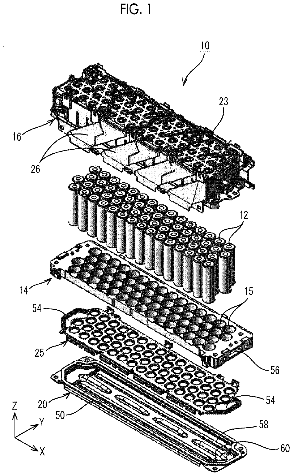
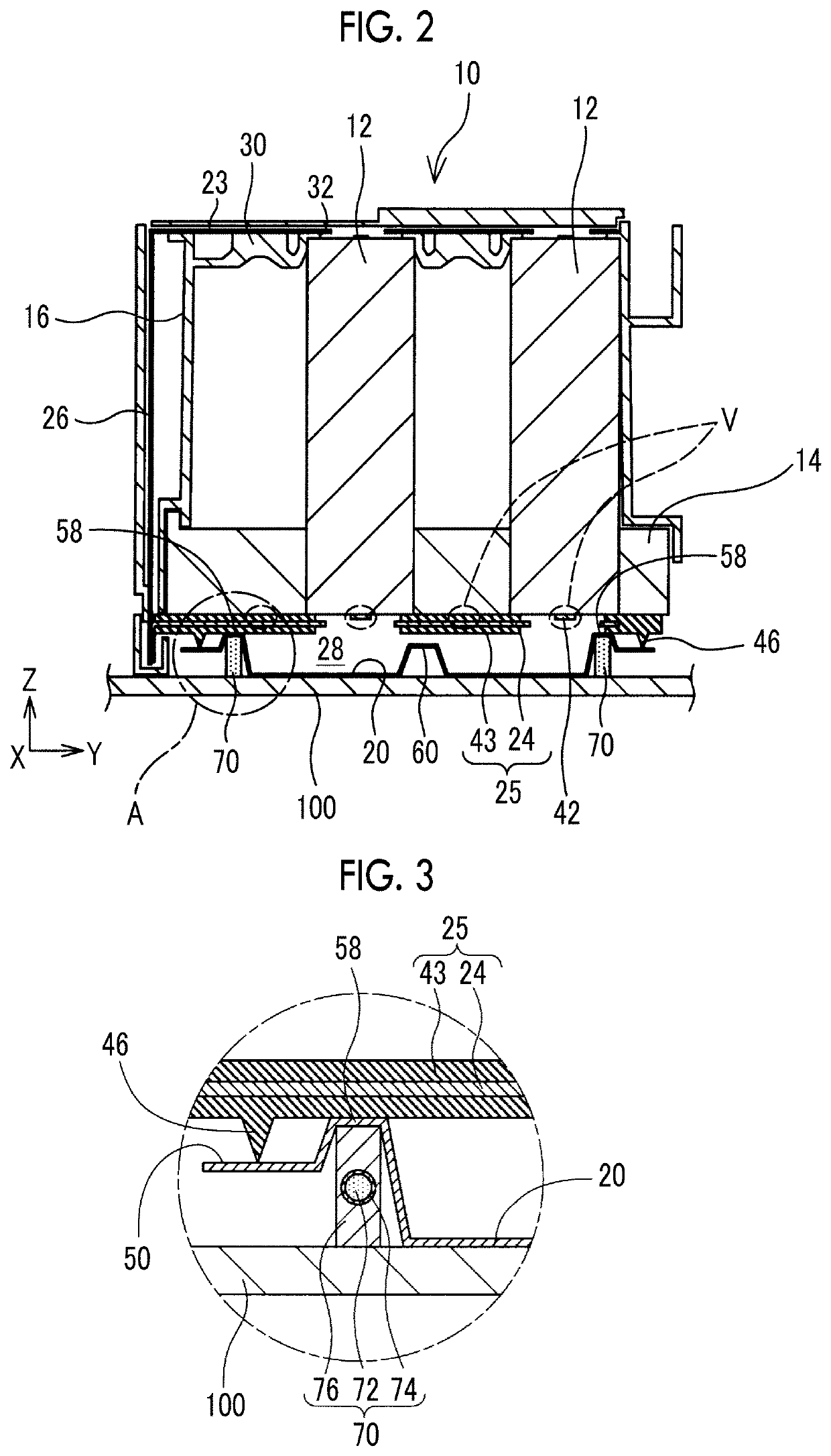
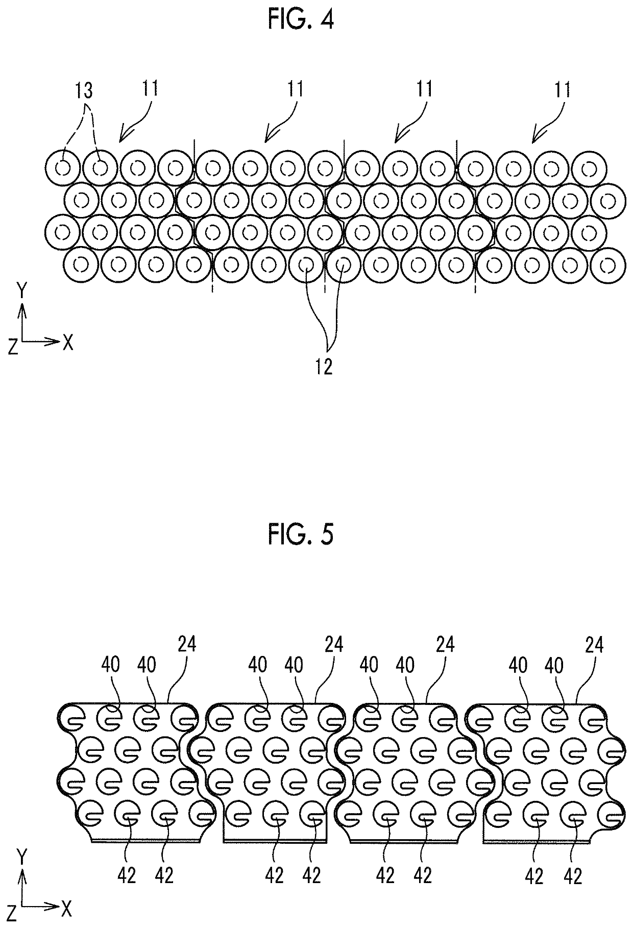
[0035]Hereinafter, the configuration of a battery pack will be described with reference to the accompanying drawings. FIG. 1 is an exploded perspective view of each battery module 10 that is incorporated in the battery pack; FIG. 2 is a cross-sectional view of the battery module 10, taken along a YZ plane. FIG. 3 is an enlarged vie w of portion A in FIG. 2. In the following description, the longitudinal direction of the battery module 10 is referred to as X direction, the axial direction of each single cell 12 is referred to as Z direction, and a direction perpendicular to the X direction and the Z direction is referred to as Y direction.

[0036]The battery pack is used as a power supply for an electric vehicle, a hybrid vehicle or a power-assisted bicycle, or a power supply for an electrical apparatus. The battery pack is formed such that one or more battery modules 10 are mounted in a pack case. The pack case is formed by assembling heat-conductive frames 100 made of a material havi...


PUM

PropertyMeasurementUnit
shapeaaaaaaaaaa
conductiveaaaaaaaaaa
heat-conductiveaaaaaaaaaa

Abstract

A battery module includes a plurality of single cells, a battery chamber, an exhaust chamber, a partition wall, a smoke exhaust cover and a seal member. The exhaust chamber is provided adjacently to the battery chamber. Gas released from the single cells flows through the exhaust chamber. The exhaust chamber has one or more exhaust holes configured to release the gas to an outside. The partition wall isolates the exhaust chamber and the battery chamber from each other. The smoke exhaust cover is arranged so as to lace the partition wall. The exhaust chamber is surrounded by the partition wall, the smoke exhaust cover and the seal member. The smoke exhaust cover has a protective protrusion at a location between the seal member and the exhaust valves adjacent to the seal member. The protective protrusion is configured upright from the smoke exhaust cover toward the partition wall.

Description

CROSS-REFERENCE TO RELATED APPLICATIONS[0001]This application claims priority to Japanese Patent Application No. 2017-022922 filed on Feb. 10, 2017, which is incorporated herein by reference in its entirety including the specification, drawings and abstract.BACKGROUND1. Technical Field[0002]The disclosure relates to a battery module and a battery pack that includes one or more battery modules each including a plurality of single cells.2. Description of Related Art[0003]Conventionally, there has been suggested that a plurality of single cells are assembled to form a battery module and, in addition, one or more battery modules are assembled to form a battery pack. The thus configured battery pack is widely used as a power supply for an electric vehicle, a hybrid vehicle or a power-assisted bicycle, or a power supply for an electrical apparatus.[0004]Incidentally, there is known that each single cell that is used in such a battery pack generates gas when an abnormal reaction occurs and...

Claims


Application Information

Patent Timeline
Patent Type & Authority Patents(United States)
IPC IPC(8): H01M50/342H01M10/615H01M10/6571H01M50/20H01M50/30H01M10/625H01M10/643H01M10/0525H01M50/213H01M50/224H01M50/271
CPCH01M50/3425H01M10/615H01M10/625H01M10/643H01M10/6571H01M50/20H01M50/30H01M50/342H01M10/0525H01M2220/20Y02E60/10Y02T10/70H01M50/325H01M50/271H01M50/224H01M50/213
Inventor MORIOKA, SATOSHI
Owner TOYOTA JIDOSHA KK
Learn More