
Adaptive autonomous aircraft system with modular payload systems

a payload system and autonomous technology, applied in the field of autonomous aircraft systems with modular payload adaptations, can solve the problems of inability to meet the transition, inability to meet the needs of launch services industry, and inability to meet the needs of launch services, etc., to achieve the effect of high frequency, reliability, flexibility and low cos

Active Publication Date: 2021-05-04
SKYLUS JAEWON CHOI
View PDF6 Cites 6 Cited by
  • Summary
  • Abstract
  • Description
  • Claims
  • Application Information

AI Technical Summary

Benefits of technology

The patent describes an unmanned system that removes limitations on pilot performance and safety. It allows for the use of virtually any rocket, including those not rated for human use. The system has optimized trajectories, lower energy requirements, and reduced safety requirements. It can accelerate to supersonic velocities and establish self-powered flight. The system can also function as a booster stage for space launch missions, carrying more payload and being more robust against environmental influences. The autonomous functionality and modular payload system reduce the size and cost of the crew required for maintenance and operations. The system has significant flexibility, including being able to pre-integrate and readie missions for flight in a short time. The software applications, avionics, and instrumentation allow for data collection, analysis, self-reconfiguration, and optimization for every mission and payload.

Problems solved by technology

The launch services industry, however, is not equipped to handle this transition.
Accordingly, conventional launch systems were not engineered to launch with high frequency, reliability, flexibility, and low costs.
As a consequence, these conventional launch systems are not suitable for use in delivery services for many of today's satellites.
Conventional launch systems are not adaptable to major variations in cargo and are extremely expensive for several reasons.
First, conventional launch systems require specialized launch sites, equipment, and substantial crew which all drive up cost, schedule, and complexity.
Second, conventional launch systems are highly dependent on weather, which greatly influences its reliability and availability.
For commercial businesses which need to reliably access space on a specific day and time, conventional launch systems often fail.
Third, conventional launch systems are expendable incurring massive hardware costs for the launch operator.
While reusability has gained some attention from the industry in recent times, significant improvements in the economics of reusable launch systems have not yet been demonstrated in practice.
As the size of the conventional launch system scales down with the decrease in the size of the payload, the negative effects of the above-mentioned factors on the economics of launch increase.
However, since the amount of payload delivered to space is far less in the smaller launch system, the economics are significantly worse.
Furthermore, since the forces of nature, flight perturbations, and weather do not scale down with a smaller launch system, such launch system with much smaller mass inertia, far less performance margin, and lower mass fractions, resulting from the inability of individual components to scale down, face significantly reduced launch windows for successful spaceflight.
Historically, small launch systems have demonstrated a failure rates of 50% to 95% depending on which launch systems one considers “small.” When compared to the history of single digit rates of failure for the similar large launch systems, the failure rates of the smaller launch systems are unreliable and illustrates the heightened difficulties that rise when launch systems are scaled down in size.
Further considerations of other factors, including the expendable designs of small, conventional launch systems, make the economics even worse.
Flight operations are massively simplified by the modular payload systems and thus requires smaller crew resulting in large decreases in operational costs.
However, as is described in detail below, none are successful in providing the advantages they claim when reduced to practice.
The carrier aircraft are large that were not originally designed for air-launching launch vehicles and requires a specialized crew to perform its complex operations.
Furthermore, in practice, the economics and performance of such air-launch methods is actually worse than a ground launched system of equal performance.
The operational costs of large, manned carrier aircraft are very high as it's subject to flight crew safety, regulatory compliance requirements, safety requirements, and performance limitations of manned carrier aircraft systems.
One obvious way this performance loss presents itself is in the free fall drop period of the air-launched vehicle.
After the launch vehicle is released from the carrier aircraft at some elevated altitude, the launch vehicle is subject to a crucial delay prior to ignition to establish powered flight.
In other words, in practice, the air-launched vehicle loses nearly all of the kinetic and positive energy claimed by prior art.
The energy bled in this transition makes air-launch methods described in prior art worse in economics and performance in comparison to a ground launched vehicle of equal performance.
Furthermore, due to the energy lost in this transition, any claims of prior art involving air-launch on reduced gravity losses, drag losses, aerodynamic losses, and improved launch economics has been questionable at best in practice.

Method used


Image

  • Adaptive autonomous aircraft system with modular payload systems
  • Adaptive autonomous aircraft system with modular payload systems
  • Adaptive autonomous aircraft system with modular payload systems

Examples


Embodiment Construction

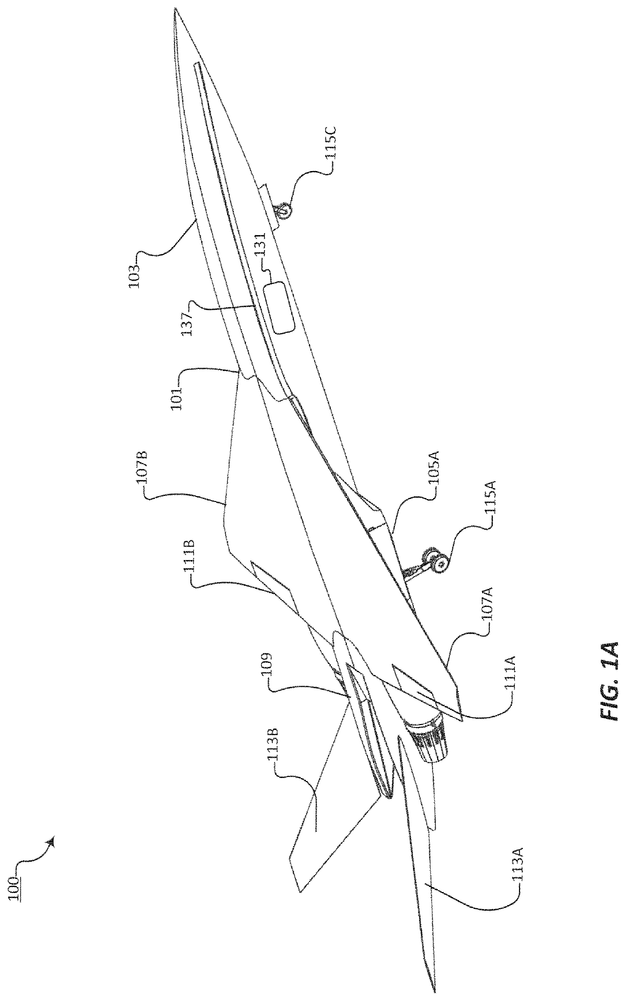
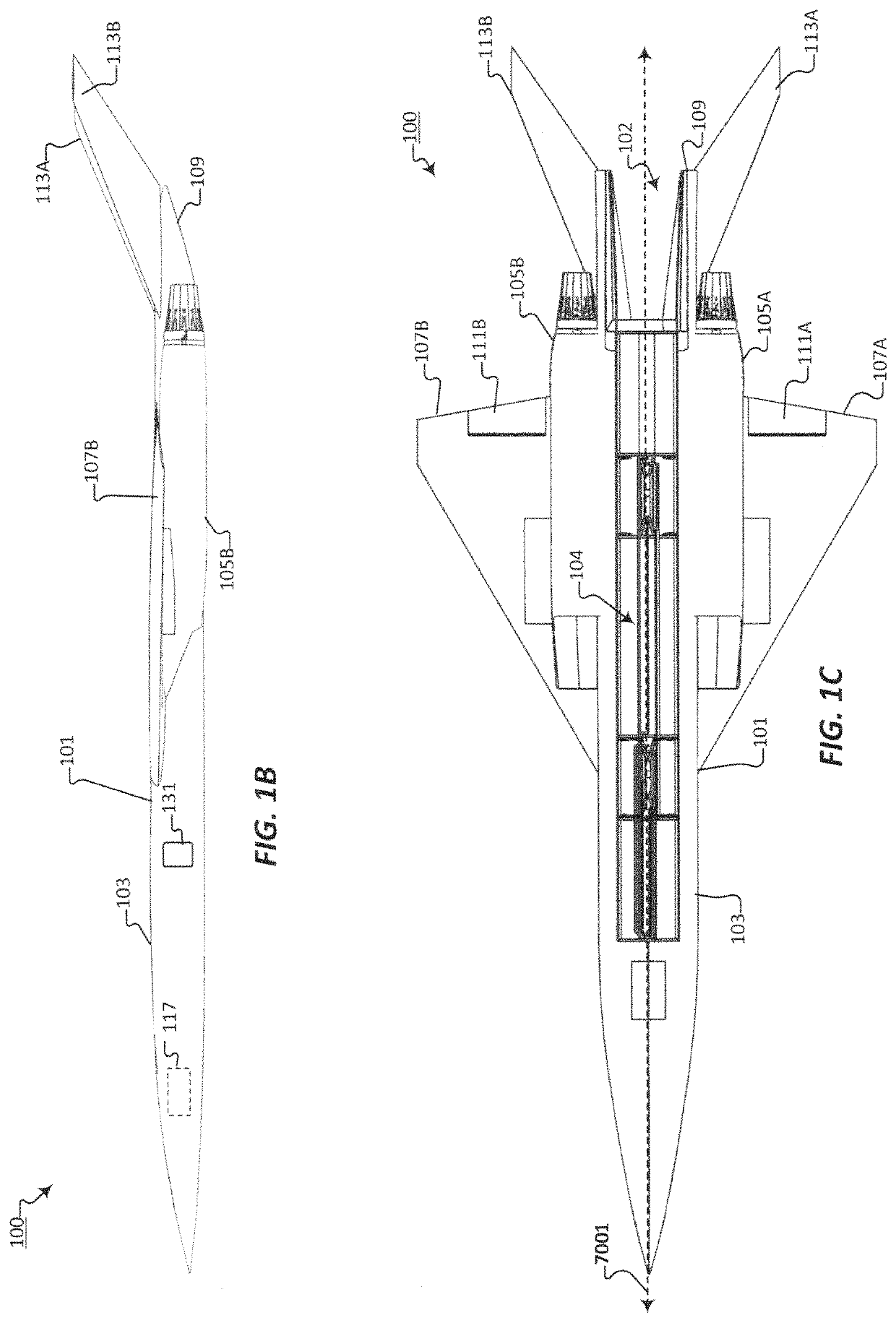
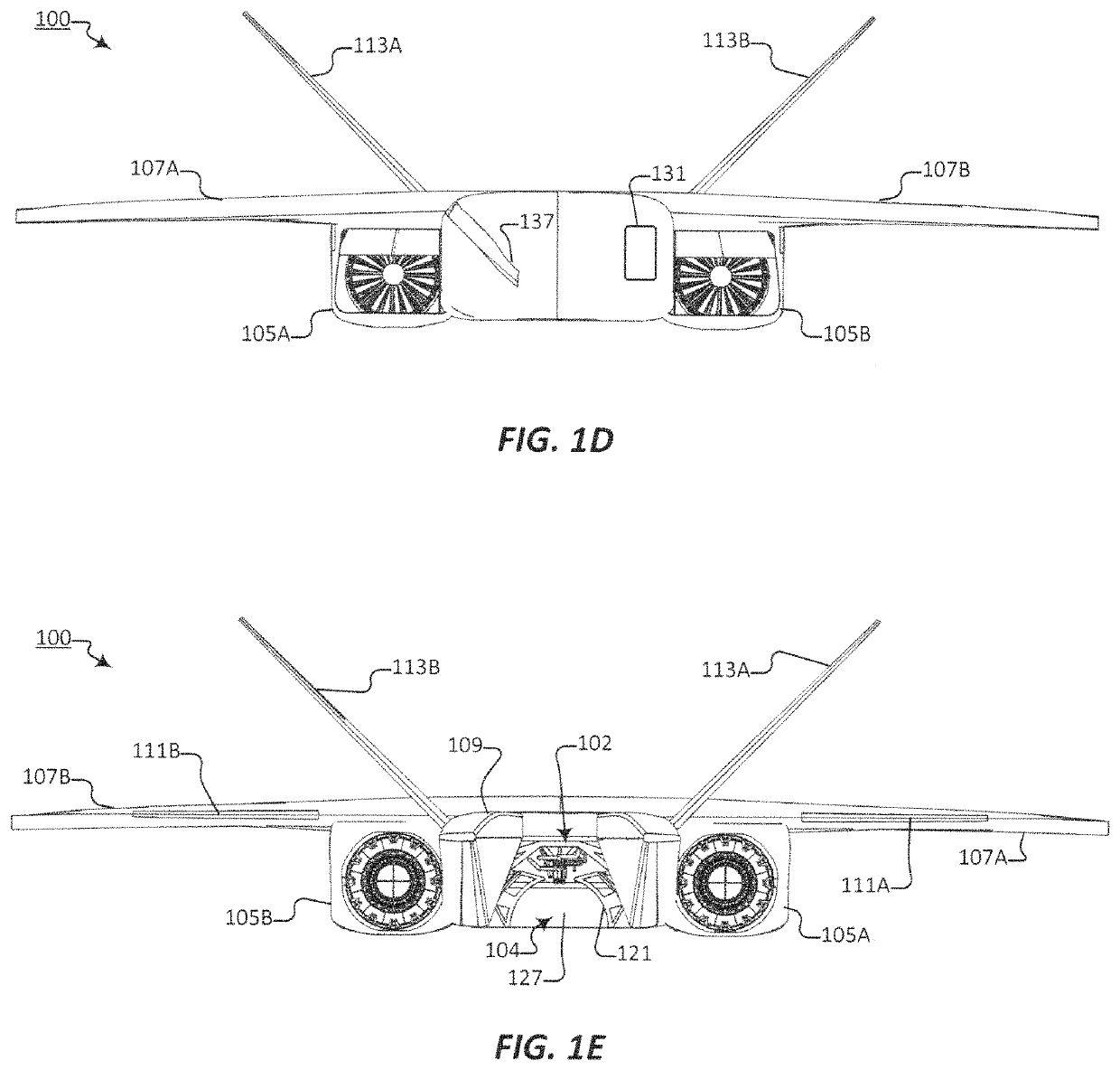
[0038]The various embodiments of the system are described below, and their advantages are best understood by referring to FIGS. 1A through 10 of the drawings. The elements of the drawings are not necessarily to scale, emphasis instead being placed upon clearly illustrating the novel features and principles of operation. Throughout the drawings, like numerals are used for like and corresponding parts of the various drawings.

[0039]Furthermore, reference in the specification to “an embodiment,”“one embodiment,”“various embodiments,” or any variant thereof means that a particular feature or aspect described in conjunction with the particular embodiment is included in at least one embodiment. Thus, the appearance of the phrases “in one embodiment,”“in another embodiment,” or variations thereof in various places throughout the specification are not necessarily all referring to its respective embodiment.

[0040]Directionally or spatially descriptive terms, such as “forward,”“rearward,”“aft,”...


PUM


Abstract

An autonomous aircraft system an airframe configured with a ventrally located payload bay open to the empennage of said airframe and payload bay terminating with a forward bulkhead which is configured to receive a payload module. The payload bay and the payload module are configured with corresponding fittings for connecting the payload module to the aircraft control systems and for securing the payload module within the payload bay.

Description

CROSS-REFERENCE TO RELATED APPLICATIONS[0001]This application claims priority to U.S. Provisional Application No. 62 / 458,711, filed Feb. 14, 2017.BACKGROUNDField[0002]The present disclosure relates generally to aerospace vehicles, and more particularly, to autonomous aircraft systems having modular payload adaptations.Description of the Problem and Related Art[0003]The rapid surge in consumer demand for mobility, connectivity, and access to content has fundamentally changed the space-based services industry. Space, as the ultimate vantage point or high ground, is becoming increasingly popular for communications, Earth observations, connectivity, and more. At the same time, there has been an emergence in technologies to drive down the cost and size of the space assets, i.e. satellites, themselves. Modern technologies demand rapid deployment with a high rate of upgrades and refresh rate. Similarly, unlike traditional satellites, many modern satellites require faster hardware updates a...

Claims


Application Information

Patent Timeline
IPC IPC(8): B64D5/00B64D1/08B64D7/08B64D1/12B64C1/10B64C30/00B64C37/02
CPCB64D5/00B64C1/10B64C30/00B64C37/02B64D1/08B64D1/12B64D7/08B64D9/00B64C1/061B64C1/22B64D1/10B64G1/005B64U50/12B64U30/10B64U80/82B64U2101/64
Inventor SKYLUS, JAEWON CHOI
Owner SKYLUS JAEWON CHOI
Learn More