
Generating virtual representations

a virtual representation and representation technology, applied in the field of generating virtual representations, can solve the problems of limited processing capacity and battery life, computationally demanding known mesh generation techniques, and ineffective devices such as smart phones and tablets, so as to reduce the amount of capture drift, accurate determination of wall planes, and accurate capture

Active Publication Date: 2021-04-27
SIGNATURIZE HLDG LTD
View PDF14 Cites 3 Cited by
  • Summary
  • Abstract
  • Description
  • Claims
  • Application Information

AI Technical Summary

Benefits of technology

This patent describes a new way to capture vertices, which allows for real-time or near-real-time generation of virtual representations of spaces without specialized equipment and skills. The technique involves converting user input into a three-dimensional coordinate and storing it as soon as it is received, reducing the effect of capture drift. This makes it easier for users to create virtual representations of spaces.

Problems solved by technology

The inventors have appreciated that some known mesh generation techniques, while effective, may be computationally demanding.
This is especially problematic for mobile devices such as smart phones and tablets, which have limited processing capabilities and battery life.
Further, the inventors have appreciated that existing vertex capture techniques limit the accessibility of virtual generation of interior spaces, and limits real-time or near-real time generation of virtual representations of spaces.

Method used


Image

  • Generating virtual representations
  • Generating virtual representations
  • Generating virtual representations

Examples


Embodiment Construction

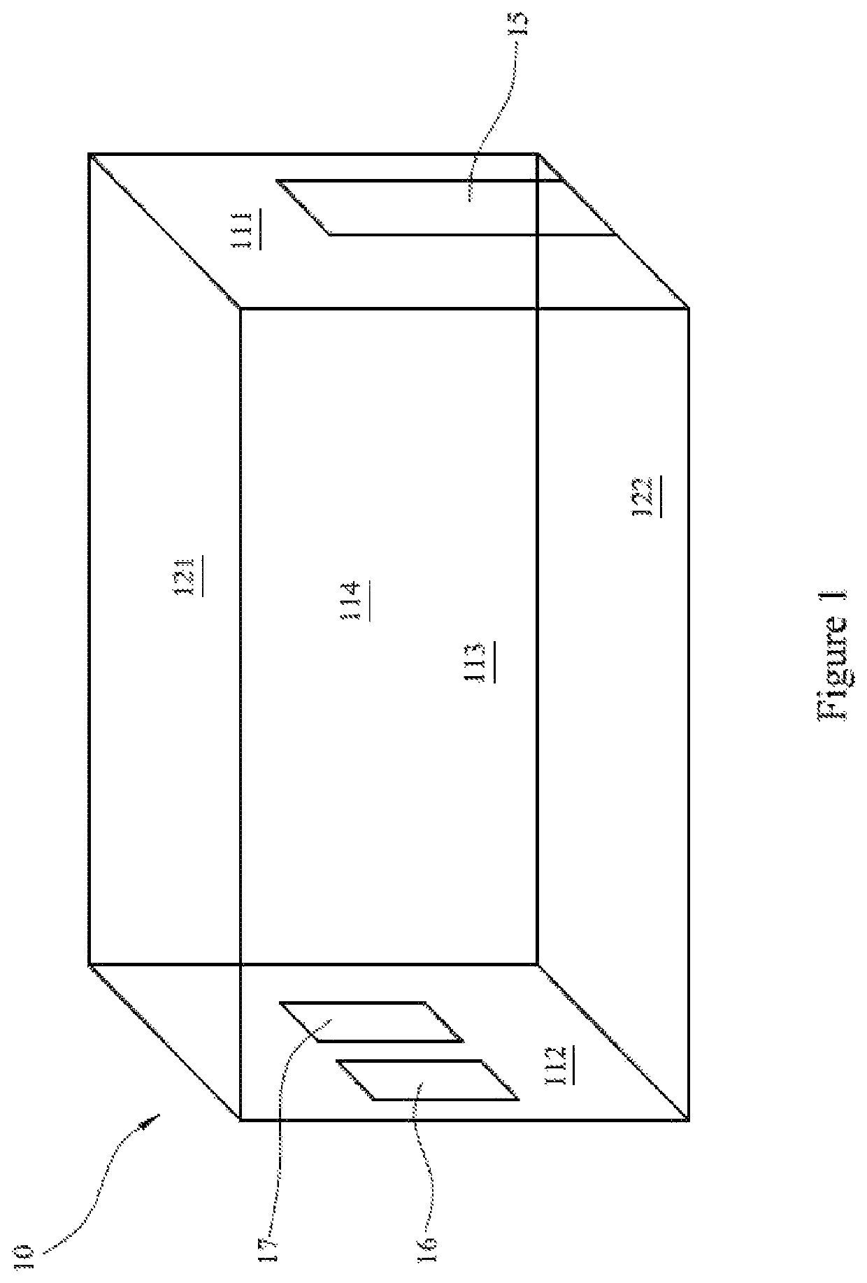
[0049]By way of an example, FIG. 1 illustrates a three-dimensional interior space 10 for which a virtual representation may be generated.

[0050]The interior space 10 includes interior surfaces 111, 112, 113, 114, 121 and 122. Interior surfaces 111-114 are walls of the interior space 10, whereas interior surface 121 is a ceiling and interior surface 122 is a floor of the interior space 10. In FIG. 1, walls 111 and 112 are opposite to each other, and walls 113 and 114 are opposite each other with wall 113 in the foreground and wall 114 in the background.

[0051]The interior surfaces of the interior space 10 have vertical edges (not numbered) where two adjacent walls meet, and horizontal edges (also not numbered) where a wall meets either the ceiling 121 or the floor 122. The interior space 10 also has corners (not numbered) where two adjacent walls meet either the ceiling 121 or the floor 122. In this description, unless the context dictates otherwise, a point said to be “located on an e...


PUM


Abstract

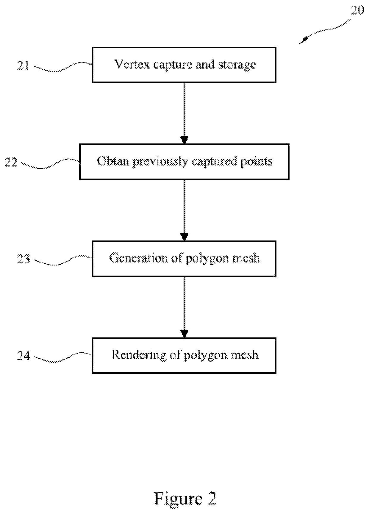
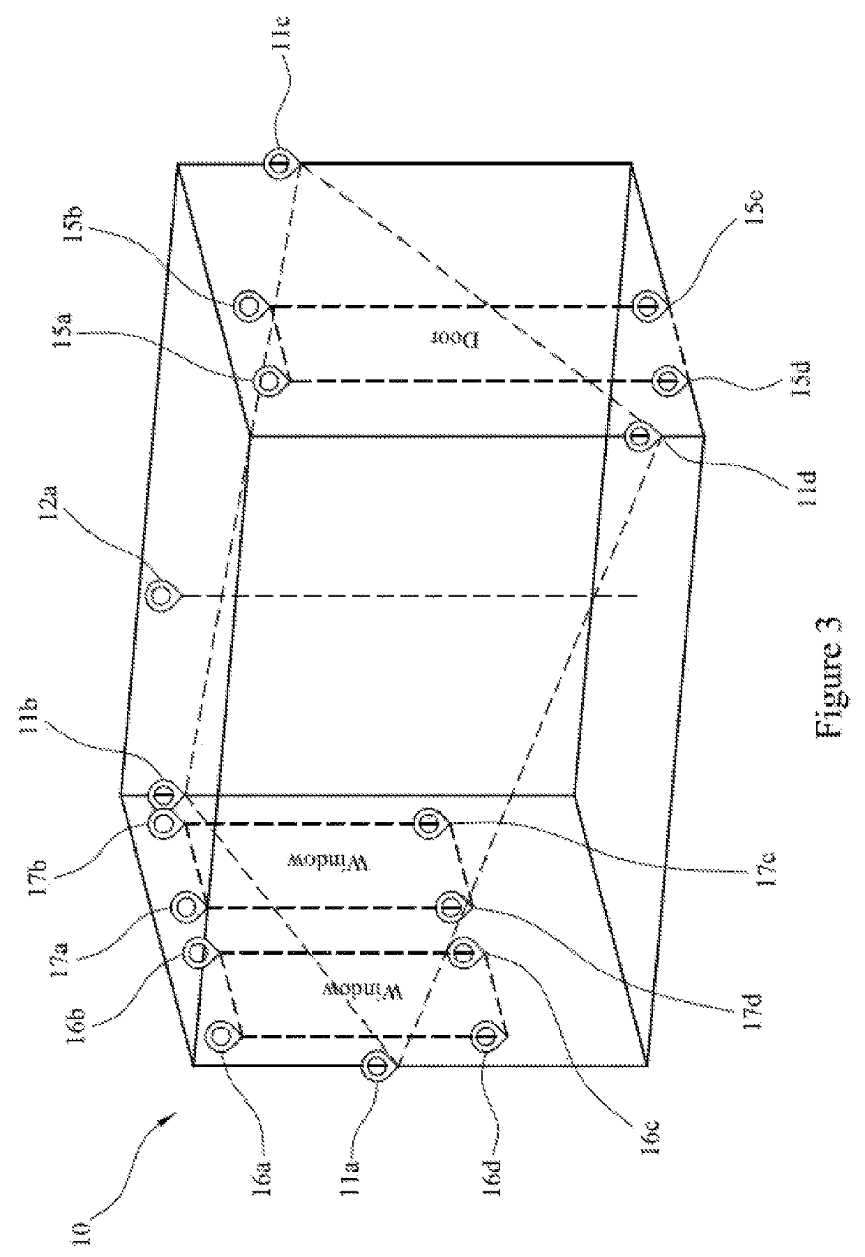
Methods, computer systems and computer programs for generating a virtual representation of an interior space such as a room are provided. Techniques for capturing and normalizing sets of points for polygon mesh generation that utilize augmented reality toolkits are also described. The methods comprise: obtaining a first set of three-dimensional coordinates and at least one further set of three-dimensional coordinates, wherein the first set of three-dimensional coordinates comprises three-dimensional coordinates representing three-dimensional positions of points located on edges of walls of the interior space, and wherein each of the at least one further set of three-dimensional coordinates comprises three-dimensional coordinates representing positions of points located on edges of an extrusion in one of the walls of the interior space; and generating a polygon mesh representing the three-dimensional shape of the interior space, wherein generating the polygon mesh comprises: using the first set of three-dimensional coordinates to determine planes representing the walls of the interior space without considering any extrusions in the walls; and for each wall with one or more extrusions, using the respective determined plane and the respective one or more of the at least one further set of three-dimensional coordinates to determine a plurality of sub-meshes that in combination represent the respective wall excluding the respective one or more extrusions; and combining the plurality of sub-meshes into a mesh representing the wall with the one or more extrusions.

Description

PRIORITY STATEMENT[0001]This application claims priority under 35 U.S.C. § 119 to UK Application No. GB1807361.9 filed on May 4, 2018, the contents of which is hereby incorporated herein by reference in its entirety.TECHNICAL FIELD[0002]The invention relates to methods, computer programs and computer systems for generating virtual representations, in particular, virtual representations of three dimensional interior spaces such as rooms.BACKGROUND[0003]Virtual representations of three dimensional objects and spaces may be generated for various reasons. For example, virtual representations of environments, buildings, objects and people may be generated for films, animation and gaming; virtual representations of anatomical objects may be generated for medical imaging; and virtual representations of buildings, rooms and objects within buildings and rooms may be generated for architectural and interior design purposes.[0004]Some techniques for generating virtual representations of object...

Claims


Application Information

Patent Timeline
Patent Type & Authority Patents(United States)
IPC IPC(8): G06T17/20
CPCG06T17/205G06T2210/04G06T17/20G06T7/50G06T19/006G06T2207/10028G06T2219/012G06T2219/2016
Inventor SINCLAIR, JONATHANLEWIS, ROBERTNICHOLL, JAMESHARRIGAN, CIARAN
Owner SIGNATURIZE HLDG LTD
Learn More