Bone clamp with adapter for measurement aids
- Summary
- Abstract
- Description
- Claims
- Application Information
AI Technical Summary
Benefits of technology
Problems solved by technology
Method used
Image
Examples
third embodiment
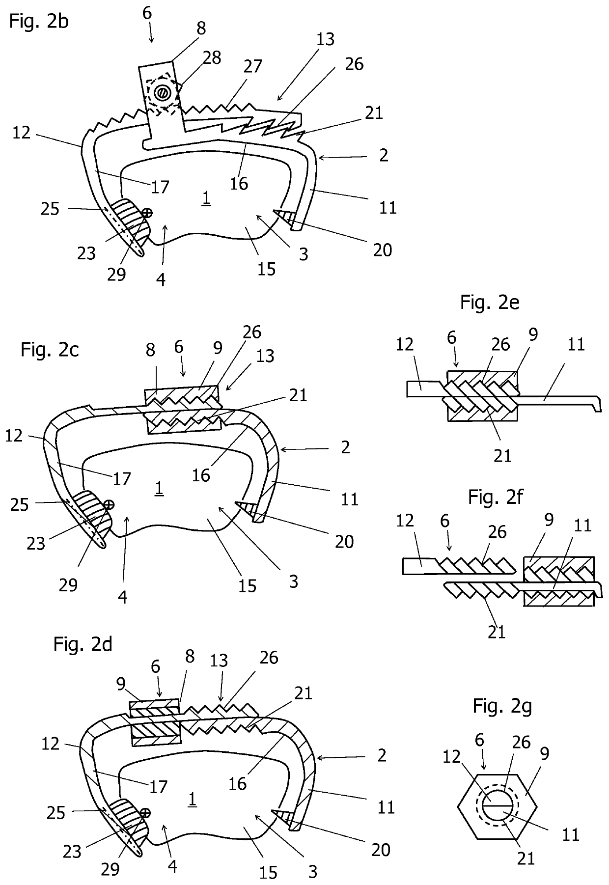
[0067]FIG. 2c shows a side view of a bone clamp 2. This embodiment differs from the previous embodiments in that the adapter 6 includes the pulling mechanism 8 and the locking mechanism 13, wherein the functions of the pulling mechanism 8 and the locking mechanism 13 are coupled. Each of the first and second clips 11, 12 contains a sawtooth-like structure 21, 26. A sawtooth-like structure is hereby representative of all forms of tooth shapes which are intended for mutual engagement. In particular, all the tooth shapes that can be used for a thread can be used. However, the sawtooth-like structures 21, 26 do not engage with each other, but are part of an external thread. As shown in FIG. 2e, the first clip 11 and the second clip 12 are provided with semi-circular cross-sections in the vicinity of the adapter 6. The sawtooth-like structures 21, 26 are threadably mounted on the outer, semi-circular surfaces of the first and second clips 11, 12. The flat surfaces of the clips 11, 12 are...
fourth embodiment
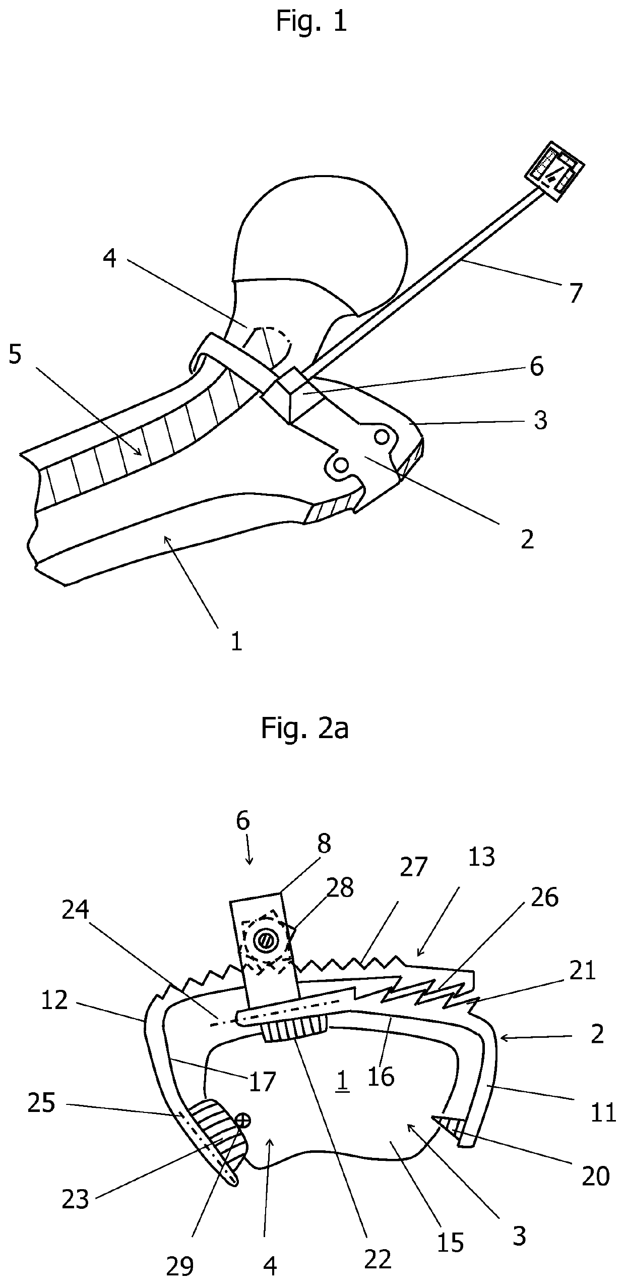
[0080]FIG. 5 shows a view of a bone clamp which contains some details regarding rotation and translation of the mounted bone clamp 2 with respect to the bone 1. The bone clamp 2 abuts the bone at three points, namely at the attachment location 51 through the spike 20, at the attachment location 52 through the sliding edge 22 and at the attachment location 53 through the sliding edge 23. The arrangement of the three attachment locations 51, 52, 53 prevents a rotation about the bone axis 55 and a tilting of the bone clamp 2 about both axes 56 and 57 which are perpendicular to the bone axis 55.
[0081]The bone axis 55 is positioned perpendicular to the plane of the drawing, as shown in FIG. 5. It is important that the spike 20 prevents any rotation of the attached bone clamp 2 about the bone axis 55 in the bone surface. Secondly, the three attachment locations 51, 52, 53 prevent translational movements parallel to the three axes 55, 56, and 57.
[0082]If the spike 20 is replaced by a slid...
fifth embodiment
[0086]FIG. 6 shows a side view of a bone clamp 2. The first and second clips 11, 12 can be coupled via the adapter 6. FIG. 6 shows the forces acting on the three attachment locations 51, 52, and 53 by a force 60 acting on the measurement aid 7. The measurement aid 7 is connected to the attached bone clamp 2 by means of the adapter 6. The measurement aid 7 has a longitudinal dimension which corresponds to a first lever arm 64. The longitudinal dimension extends from the end of the measurement aid 7 to the surface of the second clip 12 in the point where the longitudinal axis impinges on this surface. The longitudinal dimension of the measurement aid 7 is measured along a longitudinal axis 70. The longitudinal axis also extends through the adapter 6. The projection of the attachment location 53 onto the longitudinal axis 70 results in a projection length 71 in the direction of the longitudinal axis. The projection length 71 has a path center point which is obtained by dividing the pro...
PUM
 Abstract
Description
Claims
Application Information
 - R&D
- Intellectual Property
- Life Sciences
- Materials
- Tech Scout
- Unparalleled Data Quality
- Higher Quality Content
- 60% Fewer Hallucinations
Browse by: Latest US Patents, China's latest patents, Technical Efficacy Thesaurus, Application Domain, Technology Topic, Popular Technical Reports.
© 2025 PatSnap. All rights reserved.Legal|Privacy policy|Modern Slavery Act Transparency Statement|Sitemap|About US| Contact US: help@patsnap.com


