
Driver circuit, light-emitting display device, and driving method

a technology of light-emitting display device and driver circuit, which is applied in the direction of semiconductor devices, instruments, electrical apparatus, etc., can solve problems such as degrading image quality, and achieve the effects of accurate compensation of luminance deviation, accurate detection of luminance deviation among subpixels, and improved image quality

Active Publication Date: 2021-04-06
LG DISPLAY CO LTD
View PDF19 Cites 2 Cited by
  • Summary
  • Abstract
  • Description
  • Claims
  • Application Information

AI Technical Summary

Benefits of technology

The present patent provides a technology to detect and compensate for differences in brightness among pixels in a display panel. This technology can reduce sensing errors and improve image quality. Additionally, it can accurately perform sensing operations in real-time during video driving.

Problems solved by technology

Consequently, the subpixels may have different levels of luminance (non-uniform luminance), thereby degrading image quality.

Method used


Image

  • Driver circuit, light-emitting display device, and driving method
  • Driver circuit, light-emitting display device, and driving method
  • Driver circuit, light-emitting display device, and driving method

Examples


Embodiment Construction

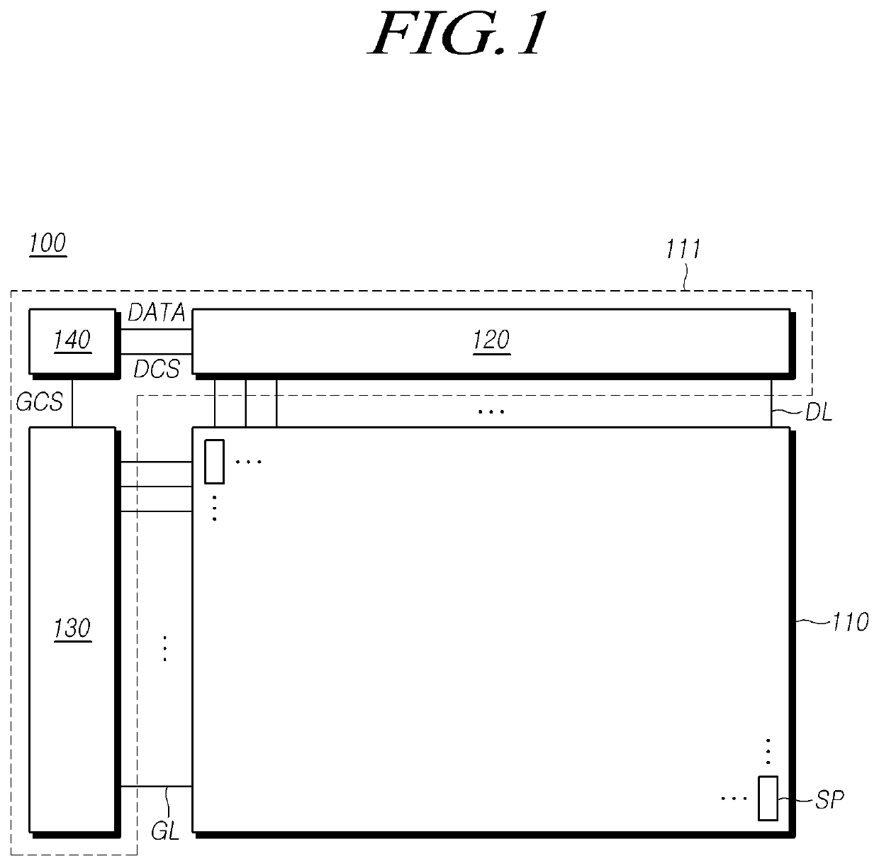
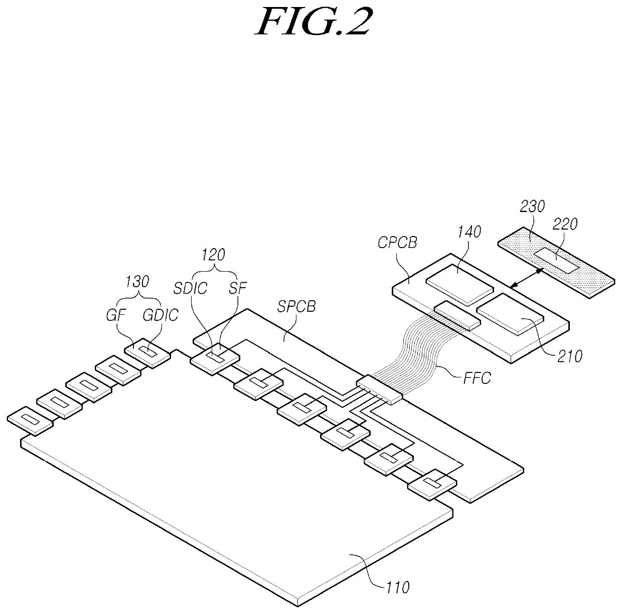
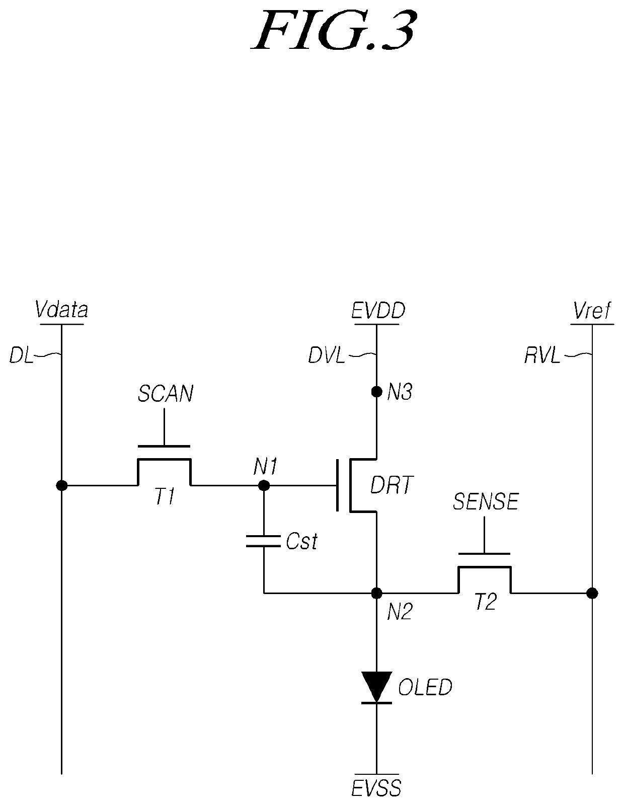
[0068]Hereinafter, reference will be made to embodiments of the present disclosure in detail, examples of which are illustrated in the accompanying drawings. Throughout this document, reference should be made to the drawings, in which the same reference numerals and symbols will be used to designate the same or like components. In the following description of the present disclosure, detailed descriptions of known functions and components incorporated herein will be omitted in the case that the subject matter of the present disclosure may be rendered unclear thereby.

[0069]It will also be understood that, while terms, such as “first,”“second,”“A,”“B,”“(a),” and “(b),” may be used herein to describe various elements, such terms are merely used to distinguish one element from other elements. The substance, sequence, order, or number of such elements is not limited by these terms. It will be understood that when an element is referred to as being “connected to” or “coupled to” another el...


PUM

PropertyMeasurementUnit
voltageaaaaaaaaaa
luminous efficiencyaaaaaaaaaa
luminanceaaaaaaaaaa

Abstract

The present disclosure describes a driver circuit, a light-emitting display device, and a driving method. Even in the case that other video control driving, e.g., fake data insertion driving, is performed during sensing driving, the sensing is not influenced by the other video control driving, e.g., fake data insertion driving. Sensing errors are prevented, and image quality is improved.

Description

CROSS REFERENCE TO RELATED APPLICATION[0001]This application claims priority to Korean Patent Application No. 10-2018-0091237, filed on Aug. 6, 2018, which is hereby incorporated by reference for all purposes as if fully set forth herein.BACKGROUNDTechnical Field[0002]The present disclosure embodiments relates to a driver circuit, a light-emitting display device, and a driving method.Description of the Related Art[0003]Organic light-emitting display devices that have recently come into prominence have advantageous features, such as a rapid response rate, high luminous efficiency, high luminance, and a wide viewing angle, since organic light-emitting diodes (OLEDs) able to emit light themselves are used therein.[0004]In such a light-emitting display device, a plurality of subpixels respectively including a light-emitting diode and a driver transistor driving the light-emitting diode are arrayed in the form of a matrix, and brightness levels of subpixels, among the plurality of subpix...

Claims


Application Information

Patent Timeline
Patent Type & Authority Patents(United States)
IPC IPC(8): G09G3/3291G09G3/3266H01M50/209H01M50/242
CPCG09G3/3291G09G3/3266G09G2300/0413G09G2300/0426G09G2300/0439G09G3/3258G09G3/3275G09G2300/0819G09G2300/0842G09G2300/0861G09G2320/029G09G2320/045G09G2310/08G09G3/32G09G2320/0209H10K59/12
Inventor KANG, MINHYUNGMIWA, KOICHI
Owner LG DISPLAY CO LTD
Learn More