Method and camera arrangement for measuring a movement of a person

a technology of camera and movement, applied in the field of method and camera arrangement for measuring the movement of a person, can solve the problems of limiting the performance of tof cameras, erroneous measurements, and giving erroneous measurements

Active Publication Date: 2021-03-30
PHOTON SPORTS TECH AB
View PDF16 Cites 1 Cited by
  • Summary
  • Abstract
  • Description
  • Claims
  • Application Information

AI Technical Summary

Benefits of technology

[0014]By assuring that there are pixels which are neither over- nor underexposed, a distance measurement is enabled for larger ranges of distances. This allows to extend the range of distances for which the arrangement can be used. Thus, a larger flexibility when using the camera arrangement and a larger possible area of application for the camera arrangement is achieved.
[0027]In one example, the method further comprises the step of compensating for potential wrapping based on at least one previously determined distance. This allows for a more accurate distance measurement.

Problems solved by technology

It has also turned out that another effect limiting the performance of TOF cameras, both valid for continuous wave TOF and pulsed TOF cameras, is partial reflection.
This may lead to erroneous measurements and is particularly evident when measuring less bright objects at longer distances when bright objects are present within the illuminated area(s).
It has further been turned out that for many existing time of flight cameras / sensors pixels imaged at or near an edge between two objects or two parts of the same object can give erroneous measurements.

Method used


Image

  • Method and camera arrangement for measuring a movement of a person
  • Method and camera arrangement for measuring a movement of a person
  • Method and camera arrangement for measuring a movement of a person

Examples


first embodiment

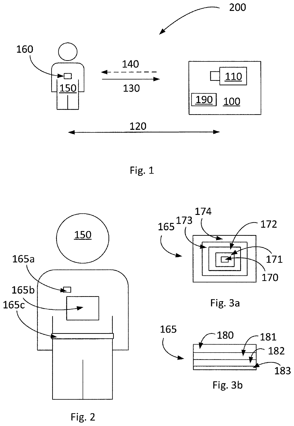
[0061]In a first embodiment, the retro-reflective element 165 and / or the area 160 is rather small compared to the size of the person. This is illustrated by element 165a. This allows for a precise measurement of a part of the person. As an example, the retro-reflective element 165 and / or the area 160 can be placed on an arm, a leg, a hand, a part of the breast, or the like. This allows for measuring exactly that part of the person where the retro-reflective element 165 and / or the area 160 is placed. As an example, when analysing high jump, it might be important to analyse how different parts of the body of the person move in relation to each other. In that case it might be advantageous to put one or several rather small marker(s) / area(s) on one or several specific part(s) of the person.

second embodiment

[0062]In a second embodiment, the retro-reflective element 165 and / or the area 160 is rather big and covers a considerably part of the person, such as, for example, a considerable part of the breast or the back of a person. This is illustrated by element 165b. This might be an advantageous arrangement for measurements in the direction to and / or from the camera, such as, for example, sprints. For such kind of sports it might be enough to analyse how the torso moves.

third embodiment

[0063]In a third embodiment, the retro-reflective element 165 and / or the area 160 is shaped in the form of a belt. This is illustrated by element 165c. This might be advantageous for movements in different directions, such as team sports, for example football, handball, volleyball, or the like.

[0064]FIGS. 3a and 3b show, in a schematic way, embodiments of a light transmitter which can be used in connection to the present disclosure. The light transmitter is illustrated in the form of a retro-reflective marker 165. However, what is said regarding the marker 165 easily applies to other light transmitters. The retro-reflective marker 165 can comprise a number of zones, such as at least two different zones. There is no limit in the number of zones. The different zones can have different reflectance. The different zones can be adapted in their reflectance to assure that at least one of the zones reflects a suitable amount of light to the camera. A suitable amount of light is an amount of...


PUM

PropertyMeasurementUnit
distancesaaaaaaaaaa
modulation frequencyaaaaaaaaaa
distanceaaaaaaaaaa

Abstract

The present disclosure relates to a camera arrangement (100) for measuring a movement of a person (150). The camera arrangement (100) comprises a camera (110) and is arranged to repeatedly determine at least one distance (120) between at least one area (160) on the person (150) and corresponding pixels in the camera (110) based on light (130) received from the at least one area (160). The camera arrangement (100) is adapted to receive different signal strengths between the corresponding pixels in the camera (110) and pixels in the vicinity of the corresponding pixels so that at least some of the corresponding pixels and the pixels in the vicinity of the corresponding pixels are neither over- nor underexposed. The camera arrangement (100) is adapted to base the determining of the at least one distance (120) on at least some of the corresponding pixels and the pixels in the vicinity of the corresponding pixels which are neither over- nor underexposed.

Description

CROSS-REFERENCE TO RELATED APPLICATION[0001]This application is a 35 U.S.C. § 371 national stage application of PCT Application No. PCT / SE2018 / 050543 filed on May 30, 2018, entitled “METHOD AND CAMERA ARRANGEMENT FOR MEASURING A MOVEMENT OF A PERSON,” which claims priority to Swedish Patent Application No. 1750669-2 filed on May 30, 2017, each of which are incorporated herein in their entirety by reference.TECHNICAL FIELD[0002]The present disclosure relates to a method and a camera arrangement for measuring a movement of a person. The present disclosure further relates to a system and a computer program product for measuring a movement of a person.BACKGROUND ART[0003]Movements of persons need to be analysed in different areas such as physiotherapy or sports. By analysing the movement of a person one can, for example, decide what kind of training needs to be performed. Even in other areas such as some kind of electronic games the movement of a person needs to be analysed.[0004]There ...

Claims


Application Information

Patent Timeline
Patent Type & Authority Patents(United States)
IPC IPC(8): H04N5/232G06T7/246G06T7/50G01S17/894G01S7/486B05C7/00B22C23/02B28B7/38
CPCG06T7/246G01S7/4868G01S17/894G06T7/50H04N5/232121G06T2207/30196G01S17/50B05C7/00B22C23/02B28B7/382G01S17/08H04N23/671
Inventor SJOBERG, JONAS
Owner PHOTON SPORTS TECH AB
Why Eureka
Try Eureka