
Light controlling apparatus and transparent display device comprising the same

a technology of light control apparatus and transparent display device, which is applied in electrical apparatus, instruments, optics, etc., can solve the problems of deterioration of brightness contrast ratio and luminance, and achieve the effect of preventing the deterioration of picture quality and non-uniform characteristics

Active Publication Date: 2021-03-30
LG DISPLAY CO LTD
View PDF3 Cites 0 Cited by
  • Summary
  • Abstract
  • Description
  • Claims
  • Application Information

AI Technical Summary

Benefits of technology

This patent is about a device that controls lighting and displays pictures. The device has a way to make sure that the voltage supplied to it is uniform, which prevents picture quality from being affected by voltage drops. The device also has a flexible circuit board that can be attached to the sides of the device to prevent voltage drops at longer distances. This prevents non-uniform characteristics from occurring and ensures good picture quality without needing extra space.

Problems solved by technology

For this reason, problems occurs in that a bright-room contrast ratio and luminance are deteriorated.

Method used


Image

  • Light controlling apparatus and transparent display device comprising the same
  • Light controlling apparatus and transparent display device comprising the same
  • Light controlling apparatus and transparent display device comprising the same

Examples


first embodiment

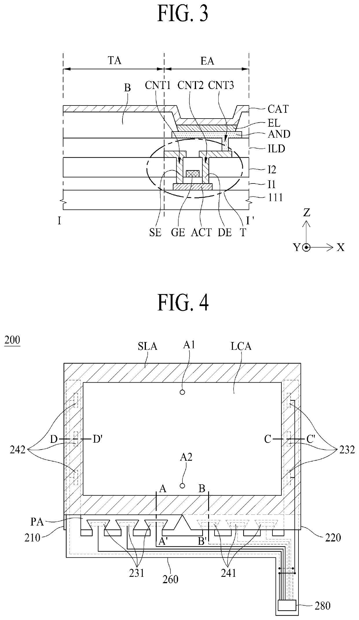
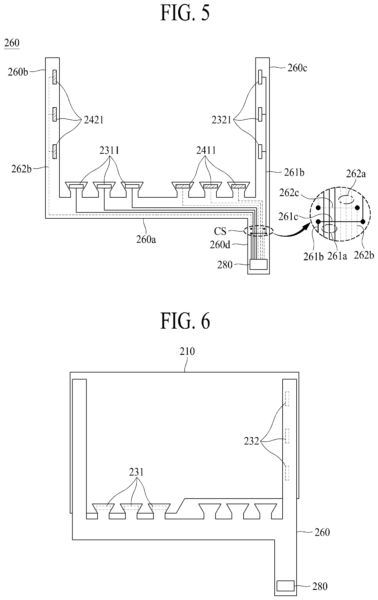
[0065]FIG. 4 is a plane view illustrating a light controlling apparatus according to the first embodiment of the present disclosure. FIG. 5 is a plane view illustrating a flexible circuit board according to the first embodiment of the present disclosure. FIG. 6 is a plane view briefly illustrating a first base film and the flexible circuit board of the light controlling apparatus according to the first embodiment of the present disclosure. FIG. 7 is a plane view briefly illustrating a second base film and the flexible circuit board of the light controlling apparatus according to the first embodiment of the present disclosure. FIG. 8 is a cross-sectional view along line A-A′ of FIG. 4, FIG. 9 is a cross-sectional view along line B-B′ of FIG. 4, FIG. 10 is a cross-sectional view along line C-C′ of FIG. 4, and FIG. 11 is a cross-sectional view along line D-D′ of FIG. 4.

[0066]The light controlling apparatus 200 can shield incident light in a light-shielding mode, and can transmit incide...

second embodiment

[0115]FIG. 12 is a plane view illustrating a light controlling apparatus according to a second embodiment of the present disclosure. FIG. 13 is a plane view illustrating a flexible circuit board according to the second embodiment of the present disclosure. FIG. 14 is a plane view briefly illustrating a first base film and the flexible circuit board of the light controlling apparatus according to the second embodiment of the present disclosure. FIG. 15 is a plane view briefly illustrating a second base film and the flexible circuit board of the light controlling apparatus according to the second embodiment of the present disclosure. FIG. 16 is a cross-sectional view along line A-A′ of FIG. 12. FIG. 17 is a cross-sectional view along line B-B′ of FIG. 12. FIG. 18 is a cross-sectional view along line C-C′ of FIG. 12. FIG. 19 is a cross-sectional view along line D-D′ of FIG. 12. FIG. 20 is a cross-sectional view along line E-E′ of FIG. 12. FIG. 21 is a cross-sectional view along line F-...


PUM

PropertyMeasurementUnit
area DAaaaaaaaaaa
refractive indexaaaaaaaaaa

Abstract

A light controlling apparatus and a transparent display device comprising the same are discussed, in which picture quality can be prevented from being deteriorated by a voltage drop. The light controlling apparatus can include a first base film including a first lower pad arranged at a first side edge on one surface and a second lower pad arranged at a second side edge on the one surface; a second base film including a first upper pad arranged at a third side edge on one surface facing one surface of the first base film and a second upper pad arranged at a fourth side edge on the one surface; and a flexible circuit board including driving voltage lines electrically connected with the first and second lower pads and common voltage lines electrically connected with the first and second upper pads.

Description

CROSS REFERENCE TO RELATED APPLICATION[0001]The present application claims the priority benefit of Korean Patent Application No. 10-2018-0061756 filed in Republic of Korea on May 30, 2018, which is hereby incorporated by reference in its entirety for all purposes as if fully set forth herein.BACKGROUND OF THE DISCLOSURETechnical Field[0002]The present disclosure relates to a light controlling apparatus and a transparent display device comprising the same.Description of the Related Art[0003]Recently, with the advancement of the information age, display devices for processing and displaying a large amount of information have been promptly developed. More particularly, various display devices have been introduced and spotlighted.[0004]Detailed examples of the display devices include liquid crystal display (LCD) devices, plasma display panel (PDP) devices, field emission display (FED) devices, electroluminescence display (ELD) devices, and organic light emitting diodes (OLED). The displ...

Claims


Application Information

Patent Timeline
Patent Type & Authority Patents(United States)
IPC IPC(8): G09G3/36G02F1/13357G02F1/1347G09G3/34H05B47/10
CPCG02F1/1336G02F1/13471G09G3/3406G09G3/3655G09G3/3659H05B47/10G02F1/134309G02F1/13306G02F1/13452H05B47/17
Inventor KIM, JAE-HYUNKIM, KIHANKIM, CHOONGHYO
Owner LG DISPLAY CO LTD
Learn More