
Ophthalmologic device and pupil state measuring method

a technology which is applied in the field of ophthalmologic devices and pupil state measuring methods, can solve the problems of difficult investigation, inability to secure the accuracy of a measurement value, and inability to measure the pupil state of the subject eye in the objective measurement, so as to prevent the complexity of the device, increase the device size, and secure the accuracy of the measurement result of the objective measurement

Active Publication Date: 2021-03-30
KK TOPCON
View PDF8 Cites 1 Cited by
  • Summary
  • Abstract
  • Description
  • Claims
  • Application Information

AI Technical Summary

Benefits of technology

The present invention provides an ophthalmologic device and a pupil state measuring method that can accurately measure the objective characteristics of the eye. By detecting the pupil state during measurement, the device can prevent errors and investigate the cause of errors. The device uses two imaging units to measure the pupil state and prevent complications, increase in device size, and costs. The pupil state measurement can be useful for optometrists and ophthalmologists in analyzing and securing the accuracy of the measurement results.

Problems solved by technology

With a conventional ophthalmologic device, when an optical characteristic of a subject eye, such as a refractive power, is objectively measured, a pupil state of the subject eye in the objective measurement has not been able to be measured.
There can be a case where a measurement luminous flux is shaded by the iris of the subject eye when miosis (contraction of pupil) arises during objective measurement, and there has been a problem that accuracy of a measurement value cannot be secured when miosis of the subject eye arises in the objective measurement.
Furthermore, there can be a case where an error caused by miosis of the subject eye arises during objective measurement, and with the conventional ophthalmologic device, it has been difficult to investigate the cause of the error.
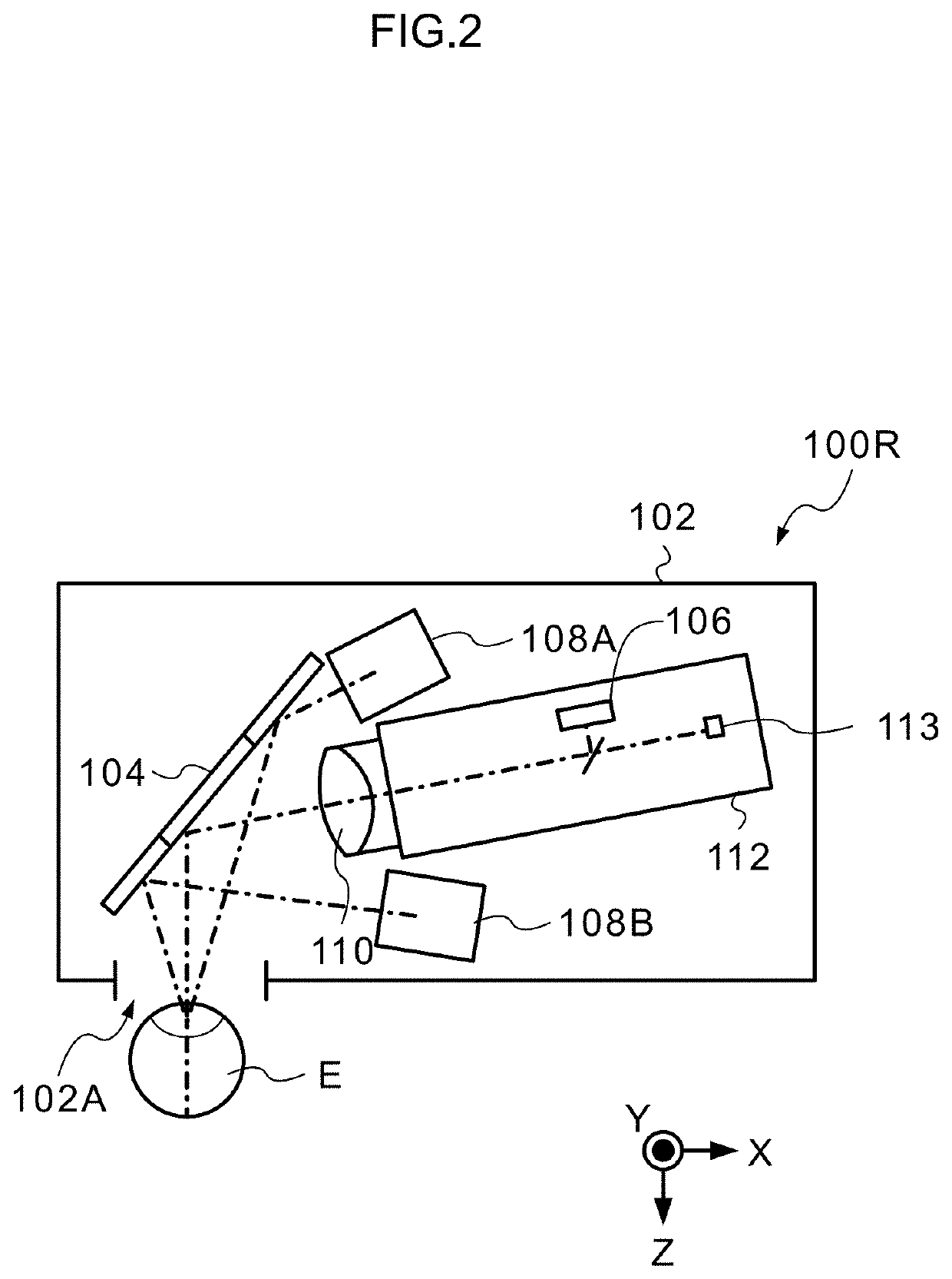
However, when measurement of the refractive power and imaging of the anterior ocular segment are performed using separate optical systems, a plurality of cameras are needed, and there has been a problem that this causes complication of the apparatus, and increase in size and costs.

Method used


Image

  • Ophthalmologic device and pupil state measuring method
  • Ophthalmologic device and pupil state measuring method
  • Ophthalmologic device and pupil state measuring method

Examples


Embodiment Construction

[0034]Hereafter, embodiments of an ophthalmologic device and a pupil state measuring method according to the present invention are described in accordance with the accompanying drawings.

Outline of Ophthalmologic Device

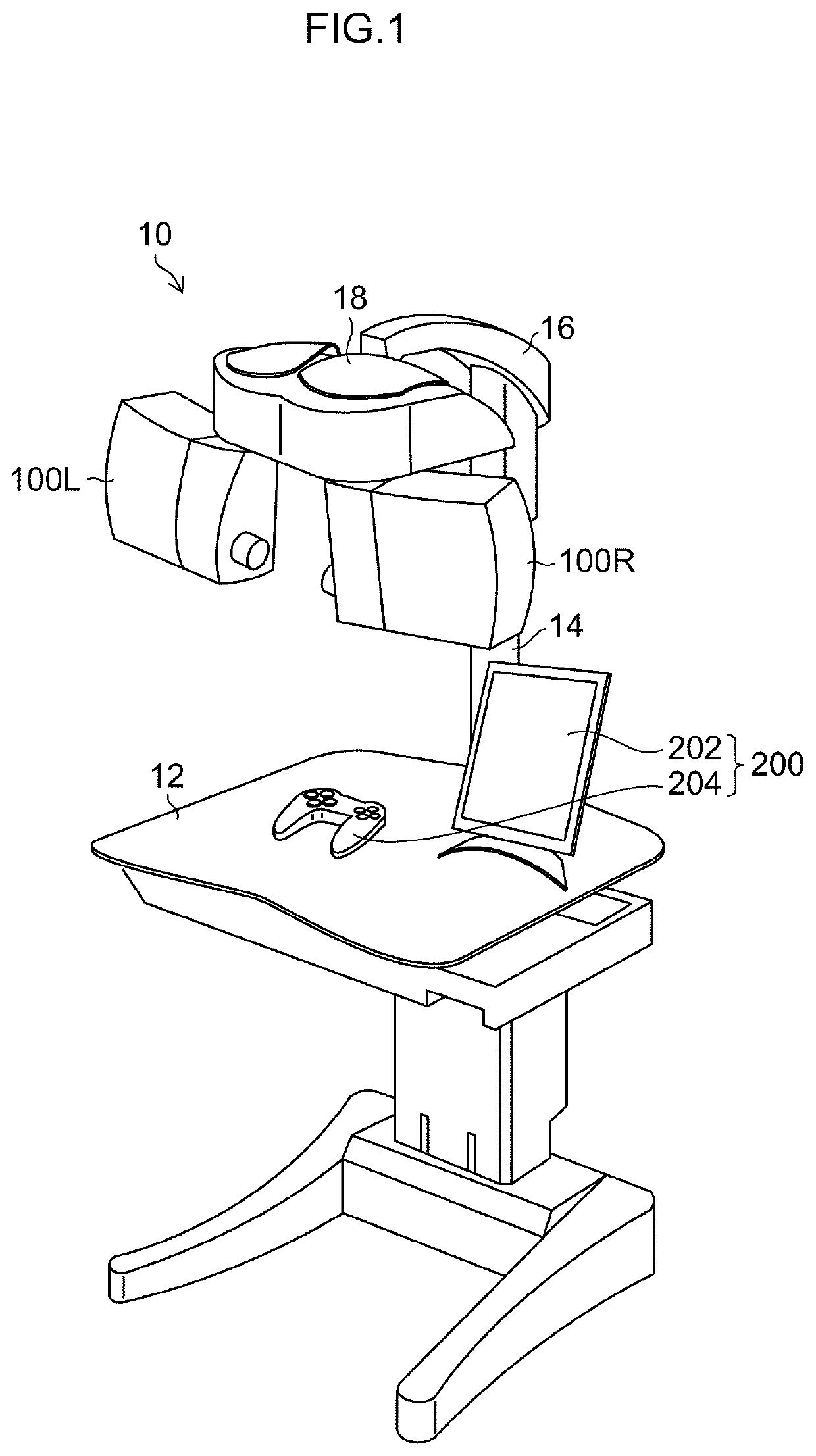
[0035]FIG. 1 is an appearance view showing an ophthalmologic device according to an embodiment of the present invention.

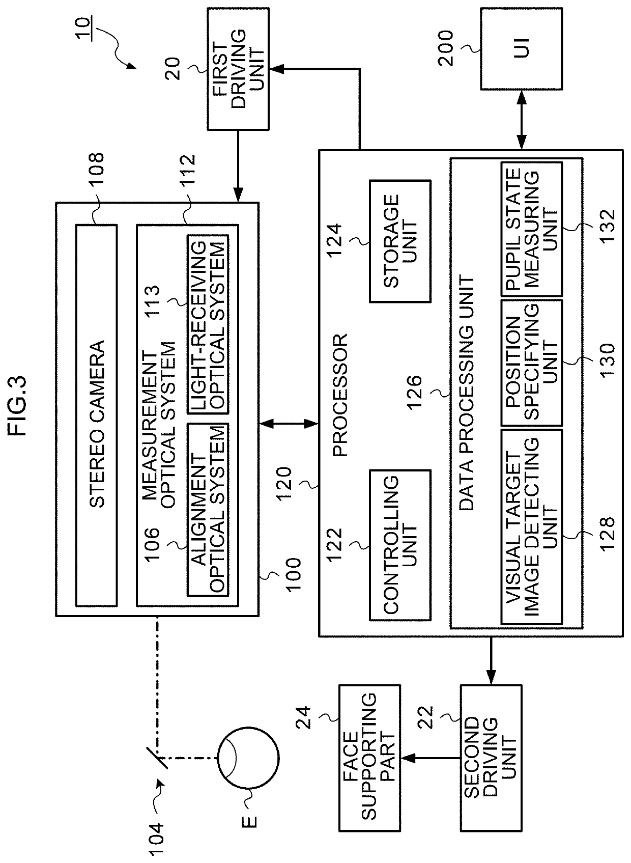
[0036]An ophthalmologic device 10 according to the present embodiment is a device which can perform both objective measurement and subjective optometry on the eyes of a subject with an optometry unit 100 (100L and 100R). In the following description, the subject and an optometrist are also referred to as “operators”.

[0037]As shown in FIG. 1, the ophthalmologic device 10 according to the present embodiment includes an optometry table 12, the optometry unit 100 (100L and 100R) and a user interface (UI) 200.

[0038]The optometry table 12 is a table adjustable in height depending on the body build and the like of the subject.

[0039]Onto the optometry table 1...


PUM


Abstract

To provide an ophthalmologic device and a pupil state measuring method capable of securing accuracy of a measurement result of objective measurement and effective for investigating the cause of an error during objective measurement. A pupil state measuring method according to the present invention includes: an ocular characteristic measuring step of objectively measuring an ocular characteristic of a subject eye of a subject; an imaging step of substantially simultaneously imaging an anterior ocular segment of the subject eye from different directions using at least two imaging units in measuring the ocular characteristic; a measuring step of analyzing at least one image of images taken by the at least two imaging units to measure a pupil state of the subject eye; and a step of performing the imaging step and the measuring step in measuring the ocular characteristic.

Description

CROSS-REFERENCE TO RELATED APPLICATIONS[0001]The present application claims priority under 35 U.S.C. § 119 to Japanese Patent Application No. 2017-188459, filed on Sep. 28, 2017. The above application is hereby expressly incorporated by reference, in its entirety, into the present application.BACKGROUND OF THE INVENTIONField of the Invention[0002]The present invention relates to an ophthalmologic device and a pupil state measuring method, and in particular, relates to an ophthalmologic device and a pupil state measuring method for measuring a pupil state of a subject eye.Description of the Related Art[0003]Japanese Patent Application Laid-Open No. 2006-263082 (which is hereinafter referred to as Patent Literature 1) discloses an ocular optical characteristic measuring apparatus including an objective ocular refractive power measuring system (30). In Patent Literature 1, an anterior ocular segment image of a subject at a target setting position is acquired by the ocular refractive po...

Claims


Application Information

Patent Timeline
Patent Type & Authority Patents(United States)
IPC IPC(8): A61B3/14A61B3/113A61B3/117A61B3/11A61B3/103
CPCA61B3/112A61B3/103A61B3/113A61B3/117A61B3/14
Inventor NAKAJIMA, MASASHI
Owner KK TOPCON
Learn More