
System, control device and method for position detection

a control device and position detection technology, applied in the field of system for position detection, can solve the problems that systems optimized for data transfer and information exchange are not necessarily optimized or even well-suited for rf-based distance measurement, and achieve the effect of improving accuracy and reliability of position detection

Active Publication Date: 2021-03-02
LIFELINE SYST INC
View PDF12 Cites 0 Cited by
  • Summary
  • Abstract
  • Description
  • Claims
  • Application Information

AI Technical Summary

Benefits of technology

The present invention provides a system and method for RF-based distance measurement that improves accuracy and reliability while optimizing power consumption. The system is particularly suited for RF-based distance measurement and is less than a by-product of mobile communication. The system processes a distance measurement quality indicator to optimize operation and achieve a reasonable level of power consumption. The system may include a quality indicator adjustment algorithm, a reflector unit, and a plurality of antennas for increased distance measurement paths. The technical effects of the present invention are improved accuracy and reliability of position detection while optimizing power consumption.

Problems solved by technology

In other words, it has been observed that systems which are optimized for data transfer and information exchange are not necessarily optimized or even well-suited for RF-based distance measurement.

Method used


Image

  • System, control device and method for position detection
  • System, control device and method for position detection
  • System, control device and method for position detection

Examples


Embodiment Construction

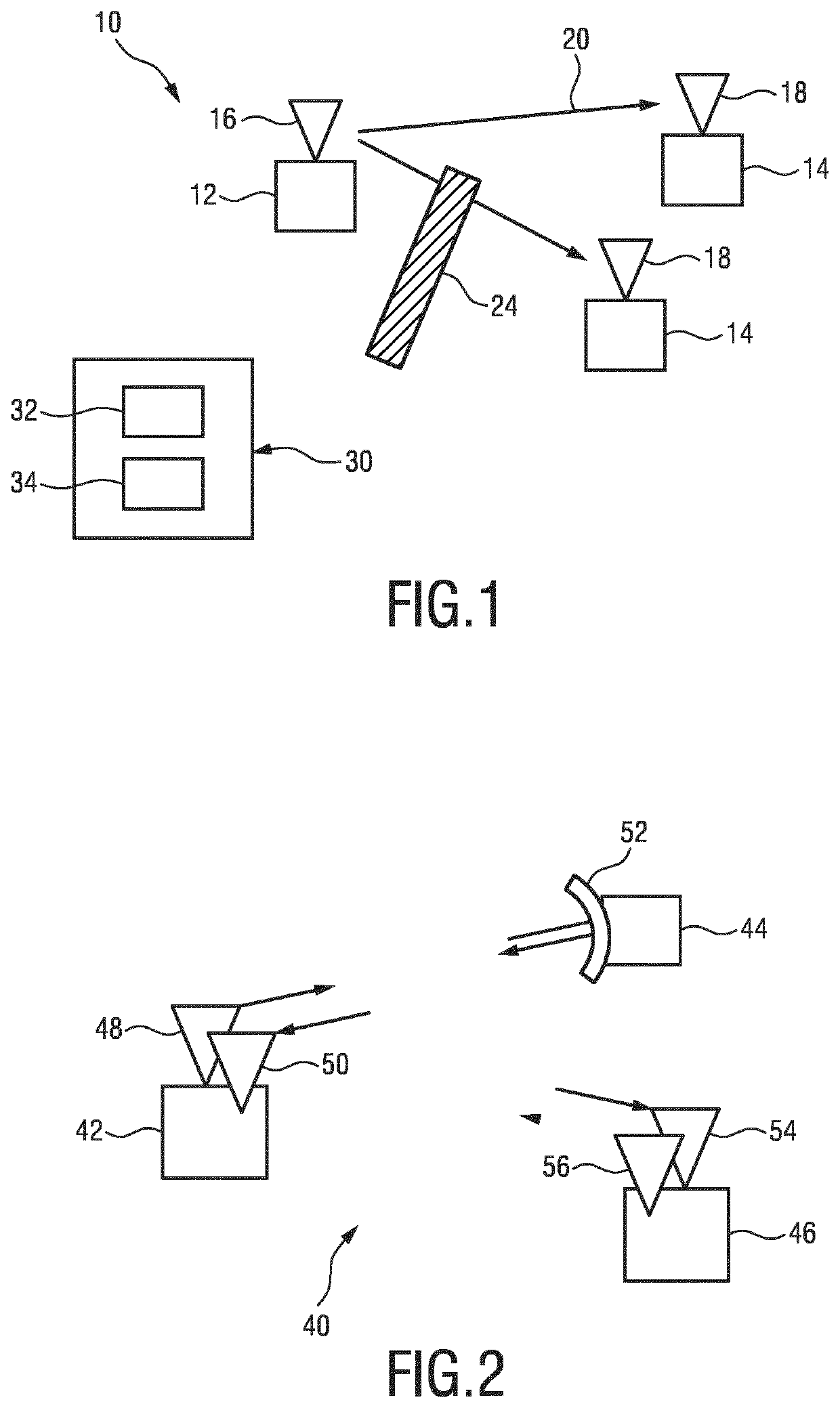
[0085]FIG. 1 shows a simplified schematic layout of an indoor position detection system 10 based on RF signals. The system 10 comprises at least one transmitting unit 12 and at least one receiving unit 14 which form an RF network or grid. Needless to say, at least one of the units 12, 14 involved may be arranged as a transceiving unit which is capable of both transmitting and receiving. The transmitting unit 12 comprises at least one transmitting antenna 16. The receiving units 14 comprise, respectively, at least one receiving antenna 18. Between the transmitting unit 12 and the receiving units 14, electromagnetic wave signals 20 are transferred. The transmitting unit 12 is arranged to transmit respective signals 20 which can be received by the receiving units 14. It is further indicated in FIG. 1 that there may be a direct line of sight between the transmitting unit 12 and at least one receiving unit 14. However, also obstacles 24 may be present, for instance walls, machinery, furn...


PUM


Abstract

The present invention relates to a system for position detection, implementing RF-based distance measurement, the system comprising at least one transmitting unit (12) arranged for transmitting an electromagnetic wave signal in the RF range, at least one receiving unit (14) arranged for receiving an electromagnetic wave signal in the RF range, wherein the transmitting unit (12) is arranged to transmit an electromagnetic wave signal specifically formed for distance measurement, and wherein the receiving unit (14) is arranged to receive the electromagnetic wave signal transmitted by the transmitting unit (12) in a direct or mediate fashion, at least one control device (30) for distance measurement based on transmitted signal information and received signal information, the control device (30) further comprising a distance measurement quality assessment unit (32), and a power consumption optimizing unit (34), wherein the distance measurement quality assessment unit (32) is arranged to derive a distance measurement quality indicator, based on distance measurement results, and wherein the power consumption optimizing unit (34) is arranged to adapt at least one transmitting parameter, based on the quality indicator.

Description

CROSS-REFERENCE TO PRIOR APPLICATIONS[0001]This application is the U.S. National Phase application under 35 U.S.C. § 371 of International Application No. PCT / EP2016 / 078090, filed on Nov. 18, 2016, which claims the benefit of European Patent Application No. 15197464.9, filed on Dec. 2, 2015. These applications are hereby incorporated by reference in their entirety herein.FIELD OF THE INVENTION[0002]The present disclosure relates to a system for position detection which is based on RF distance measurement and to a corresponding position detection method. The present disclosure further relates to a control device for a position detection system and to a patient monitoring arrangement. Further, the present disclosure relates to beneficial uses of a position detection method and system, and to a computer program which corresponds to the position detection method.BACKGROUND OF THE INVENTION[0003]RF (radio frequency)-based communication and RF-based distance measurement is widely known and...

Claims


Application Information

Patent Timeline
Patent Type & Authority Patents(United States)
IPC IPC(8): G01S5/02G01S13/87G01S5/14
CPCG01S5/0226G01S5/0221G01S13/876G01S5/14
Inventor VAN DEN DUNGEN, WILHELMUS ANDREAS MARINUS ARNOLDUS MARIA
Owner LIFELINE SYST INC
Learn More