
Method for assessing a condition of a particulate filter and exhaust system for a motor vehicle

a technology of particulate filter and exhaust system, which is applied in the direction of machines/engines, mechanical equipment, separation processes, etc., can solve the problems of non-constant pressure on the input and output side of the particulate filter in the exhaust system, rarely or never achieved during normal driving, and the operation state of the internal combustion engine. , to achieve the effect of increasing the loading of the particulate filter, and reducing the load of the par

Active Publication Date: 2021-03-02
DAIMLER AG
View PDF12 Cites 2 Cited by
  • Summary
  • Abstract
  • Description
  • Claims
  • Application Information

AI Technical Summary

Benefits of technology

Enables a simplified and reliable method for diagnosing particulate filter condition in normal driving conditions, using existing sensors to detect changes and patterns in pressure signals, ensuring regular diagnostic capability and reducing the need for high engine loads.

Problems solved by technology

Such operating states in the internal combustion engine, which are necessary for a diagnosis or a load detection, are rarely or never achieved during normal driving, however.
In addition, the existing pressure on the input and output side of the particulate filter in the exhaust system is non-constant.
If, however, deviations from the load amplitudes occur, as are then expected if the particulate filter is in order, it can be concluded that there has been a failure.
It can happen, for example, that, in a housing of the particulate filter, no filter device is incorporated, meaning the filter device is therefore removed, or that the filter device is damaged in such a way that the exhaust gas cannot penetrate the porous filter walls of the filter device.
Furthermore, a failure in the differential pressure sensor and / or the relative pressure sensor can be deduced when a pattern of frequency recorded by means of the differential pressure sensor and / or the relative pressure sensor differs from a frequency pattern of the changes in pressure to be expected on account of the operation of the internal combustion engine.
This is because the exhaust gas thereby has a high impulsivity, thus resulting in a particularly strongly pulsating exhaust gas mass flow.

Method used


Image

  • Method for assessing a condition of a particulate filter and exhaust system for a motor vehicle
  • Method for assessing a condition of a particulate filter and exhaust system for a motor vehicle
  • Method for assessing a condition of a particulate filter and exhaust system for a motor vehicle

Examples


Embodiment Construction

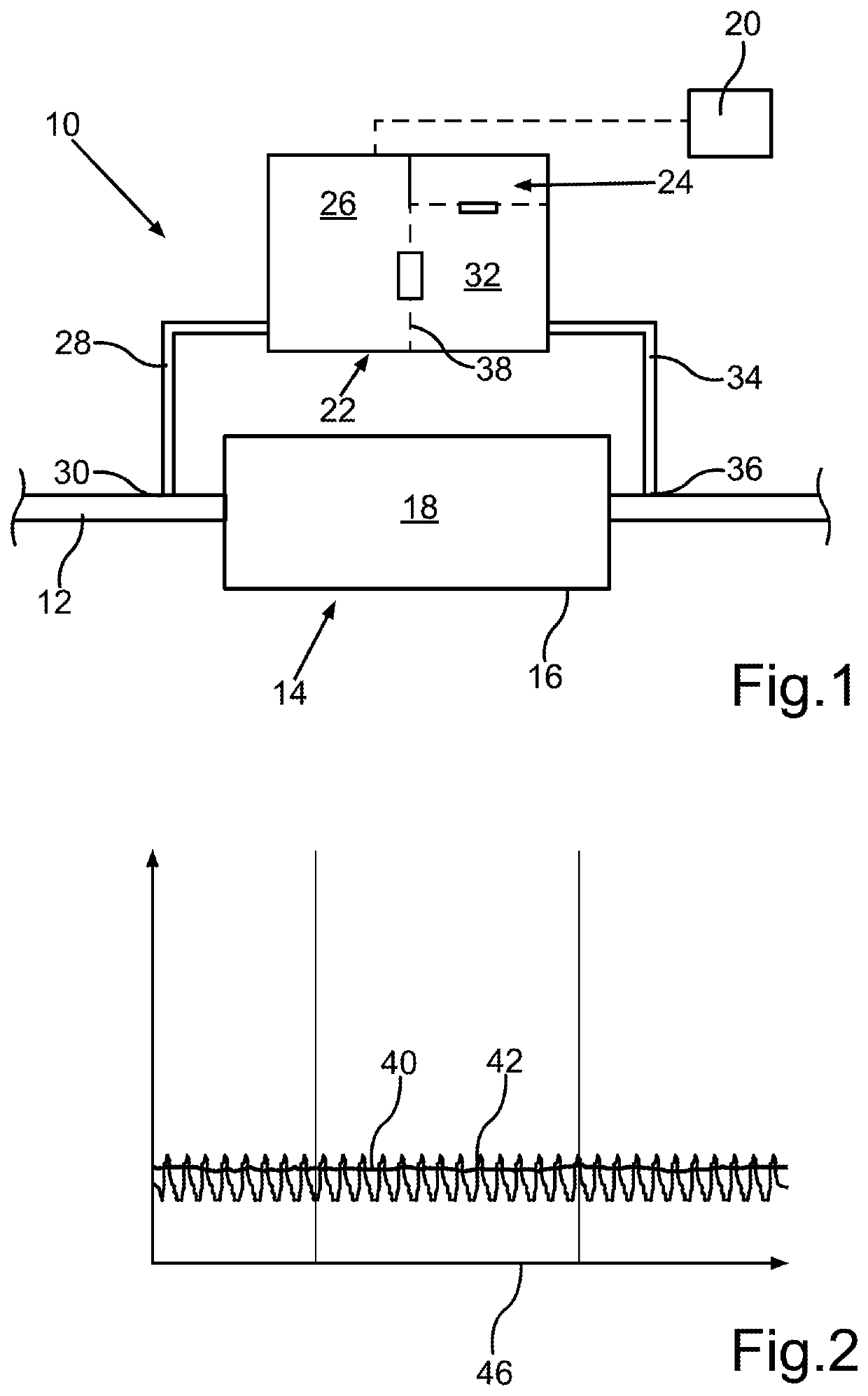
[0032]FIG. 1 shows a highly schematic representation of a section of an exhaust system 10 of a motor vehicle. The exhaust system 10 comprises an exhaust pipe 12, through which exhaust gas of an internal combustion engine (not shown) of the motor vehicle is guided to a particulate filter 14. The particulate filter 14 comprises a housing 16 and a filter device 18 arranged in the housing 16. The components of the exhaust system 10 shown in FIG. 1 are shown merely schematically and do not indicate the actual size proportions of the illustrated components relative to one another.

[0033]Presently, the condition of the particulate filter 14 is assessed by means of a control device 20, for example in the form of a controller. For this, readings are supplied to the control device 20, which are recorded by a differential pressure sensor 22 and a relative pressure sensor 24. A first chamber 26 of the differential pressure sensor 22 is fluidically connected to an input side of the particulate fi...


PUM

PropertyMeasurementUnit
differential pressure sensoraaaaaaaaaa
pressureaaaaaaaaaa
relative pressure sensoraaaaaaaaaa

Abstract

In a method for assessing a condition of a particulate filter for use in an internal combustion engine of a motor vehicle, a difference between a pressure exerted on the input side of the particulate filter and a pressure exerted on the output side of the particulate filter is recorded by a differential pressure sensor. The difference in pressure is taken into account when assessing the condition. Furthermore, the pressure exerted on the output side of the particulate filter in relation to the atmospheric pressure is recorded by a relative pressure sensor. When assessing the condition of the particulate filter, the pressure recorded by the relative pressure sensor is also taken into account. A frequency of changes in pressure and / or an amplitude load of the pressure is assessed. The invention also relates to an exhaust system for a motor vehicle.

Description

BACKGROUND AND SUMMARY OF THE INVENTION[0001]The present invention relates to a method for assessing a condition of a particulate filter for an internal combustion engine of a motor vehicle. In this regard, a difference between a pressure on the input side of the particulate filter and a pressure on the output side of the particulate filter is detected by means of a differential pressure sensor. The difference in pressure is taken into account when assessing the condition. In addition, the invention relates to an exhaust system for a motor vehicle.[0002]German Publication DE 10 2005 005 055 A1 describes a fault state detection device for an exhaust purification device of an internal combustion engine. In this regard, a differential pressure sensor is applied with the pressure applied to a front and back of a diesel particulate filter. For example, using the amplitudes of the measured values of the pressure difference, it can be determined, for example, whether a tear or break is pre...

Claims


Application Information

Patent Timeline
Patent Type & Authority Patents(United States)
IPC IPC(8): B01D46/00B01D46/44F01N11/00
CPCB01D46/0086B01D46/446F01N11/00B01D2279/30F01N2550/04F01N2900/08F01N2900/1406Y02T10/40
Inventor WUNDERLICH, KLAUSSAUTER, WERNERPEPE, ROSARIOSCHOLZ, MICHAELBAEHR, JUDITHSCHWAAB, JULIUSRAJAGOPAL, RAMAKRISHNAN
Owner DAIMLER AG
Learn More