
Personal watercraft

a technology for watercraft and personal water, applied in the field of personal watercraft, can solve the problem that the hobie eclipse does not provide separate flotation devices, and achieve the effect of preventing drag

Active Publication Date: 2021-02-23
KRAMER JAMES F
View PDF3 Cites 2 Cited by
  • Summary
  • Abstract
  • Description
  • Claims
  • Application Information

AI Technical Summary

Benefits of technology

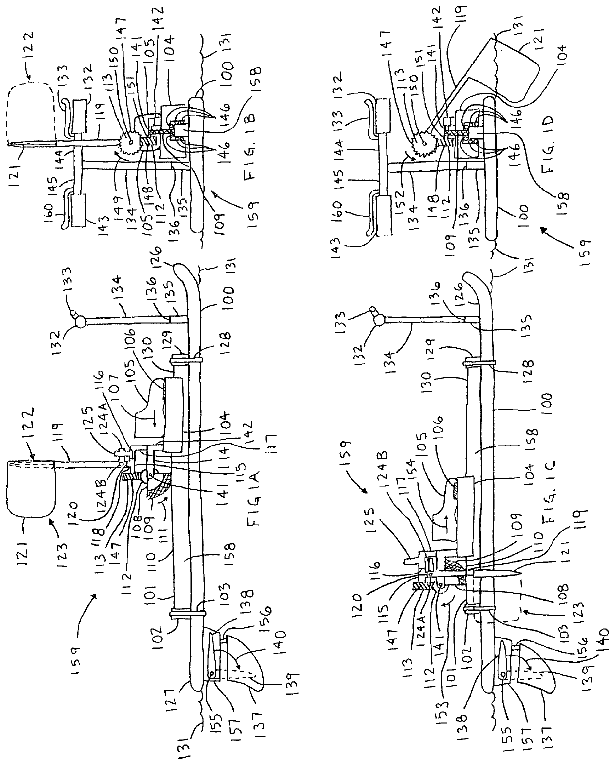
This patent describes a device called an SUP (semi-synchronous paddles) that allows a rider to stand on a platform while using paddles to move through water. The device has guides and carriages that can be used to move the rider's feet and paddles. The device also has a kick stand with wheels that can be easily rolled to the water's edge or retracted to prevent drag. The technical effects of this device include improved stability, reduced resistance, and a gliding feeling for the rider.

Problems solved by technology

Neither a standard stand-up paddle board nor a Hobie® Eclipse board with MirageDrive® allows a rider to generate thrust by sliding their feet forward and rearward.
The Hobie Eclipse does not provide separate flotation devices for each foot.

Method used


Image

  • Personal watercraft
  • Personal watercraft
  • Personal watercraft

Examples


second embodiment

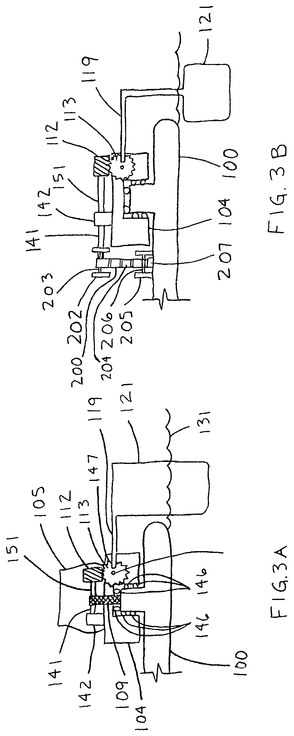
[0127]FIG. 2B provides a second embodiment for the sector, where a sector 200 is capable of rotating about the axis 141 as the axis 141 translates parallel to the rail 110. The axis 141 is supported by a carriage (not shown in FIG. 2B) that is supported by the rail 110, where the carriage is capable of translating relative to the rail 110. The sector 200 comprises an engaging portion 201 for engaging with the top portion 110 of the rail 158. Any convenient means may be used to engage the engaging portion 201 of the sector 200 with the top 110 of the rail 158. For instance, the engaging portion 201 may include an elastic region, such as rubber, that grips with the top 110 of the rail 158 as the axis 141 translates parallel to the rail 110.

[0128]As shown in FIG. 2B, sector 200 comprises rotary members on each end, such as wheels, cylinders, and the like, that rotate when in contact with the rail 110 or a shoulder of the rail 110. A first rotary member 202 rotates relative to the secto...

third embodiment

[0134]FIG. 2C provides a third embodiment for the sector, where sector 200 is capable of rotating about the axis 141 as the axis 141 translates parallel to the rail 110. The axis 141 is supported by a carriage (not shown in FIG. 2C) that is supported by the rail 110, where the carriage is capable of translating relative to the rail 110. The sector 200 comprises an engaging portion 204 for engaging with the top portion 207 of the SUP 100. In this embodiment, the engaging portion 204 may include a region with pinion teeth on the sector 200 that engages with the top rack 207 on the SUP 100 as the axis 141 translates parallel to the SUP 100.

[0135]Engagement comprising a rack and pinion is representative of a family of engaging surfaces. Such engaging surfaces may comprise any convenient engaging surfaces that allow little or no slip between them. Exemplary surfaces may also comprise interlaced protrusions, such as the illustrated rack and pinion, but may also comprise surfaces that enga...


PUM


Abstract

A personal watercraft includes a floatation member, a thrust assembly, a steering assembly, and a braking assembly. The assemblies may be actuated either mechanically or electrically. The thrust assembly is human powered, solar powered, or electric powered. The thrust, steering, and braking assemblies can be added after-market to an existing stand-up paddle board (SUP), or built into one or a plurality of SUPs during initial manufacturing. When the thrust assembly is human powered, it is leg or arm powered. When the thrust assembly is leg powered, the legs can move backward and forward in a sliding motion, up and down in a stomping fashion, or move in a loop trajectory. When the thrust assembly is arm powered, the arms can move forward / backward together or separately. The thrust assembly includes one or a plurality of paddles or flippers that are positioned to the side or under the SUP.

Description

TECHNICAL FIELD[0001]The field of this invention generally relates to personal watercraft.BACKGROUND[0002]Pelican International Inc. manufactures paddle boats. Companies which provide linear guides include Igus, Hiwin, VBX and Thomson. Neither a standard stand-up paddle board nor a Hobie® Eclipse board with MirageDrive® allows a rider to generate thrust by sliding their feet forward and rearward. The Hobie Eclipse does not provide separate flotation devices for each foot. The MirageDrive does not attach to a standard stand up paddle board.SUMMARY OF THE INVENTION[0003]The subject invention provides a personal watercraft which typically includes a floatation member for supporting a rider, typically supported entirely out of the water; although a portion of the rider may be supported in the water. Throughout this patent application, reference will be made to water, typically fresh or salt water; however, the provided watercraft is not intended to be limited to use in water, since it w...

Claims


Application Information

Patent Timeline
Patent Type & Authority Patents(United States)
IPC IPC(8): B63H16/18B63H1/36B63H25/44B63H25/06B63B32/00
CPCB63H16/18B63B32/00B63H1/36B63H25/06B63H25/44B63H2016/185B63H5/04B63H1/32B63B34/50B63B32/66B63B32/10B63B32/40B63B32/64
Inventor KRAMER, JAMES F.
Owner KRAMER JAMES F
Learn More