Optical tracking tool for navigating surgery

a tracking tool and surgical navigation technology, applied in the field of computer-aided surgery, can solve the problems of difficult to guarantee the accuracy of the surgical navigation system using the tracking tool, the small tracking range of the system, and the difficulty of a surgical navigation system to use the tracking tool, so as to improve the system accuracy, improve the effective tracking range of the system, and improve the effect of system accuracy

Active Publication Date: 2021-02-23
BEIJING TINAVI MEDICAL TECH
View PDF11 Cites 0 Cited by
  • Summary
  • Abstract
  • Description
  • Claims
  • Application Information

AI Technical Summary

Benefits of technology

[0005]In view of the above problems, an object of the present invention is to provide an optical tracking tool for navigating a surgery, with a high positioning accuracy and a large tracking range.
[0009]Due to adopting the above technical solution, the present invention has the following advantages: 1. compared with a tracking tool having a single positioning face formed by four reflective balls in the prior art, the optical tracking tool can obviously broaden an effective tracking range of a system, thereby improving system accuracy; 2. the present invention provides a connection structure for the reflective balls and the supporting faces, which can realize the precise positioning and connection between the reflective balls and the supporting faces; 3. the present invention, with simple structure and reliable performance, can be widely used in tracking and positioning of clinical surgical robots.

Problems solved by technology

The main disadvantage of this design is that the tracking range of the system is small, usually less than ±90°.
Moreover, as the accuracy of the position coordinates of the tracking tool, obtained by the optical tracking system, is related to the angle defined by the positioning face of the tracking tool and the optical axis of the binocular position sensor, the greater the angle, the worse the accuracy, and the accuracy of a surgical navigation system using the tracking tool is difficult to be guaranteed.

Method used


Image

  • Optical tracking tool for navigating surgery
  • Optical tracking tool for navigating surgery

Examples


embodiment 1

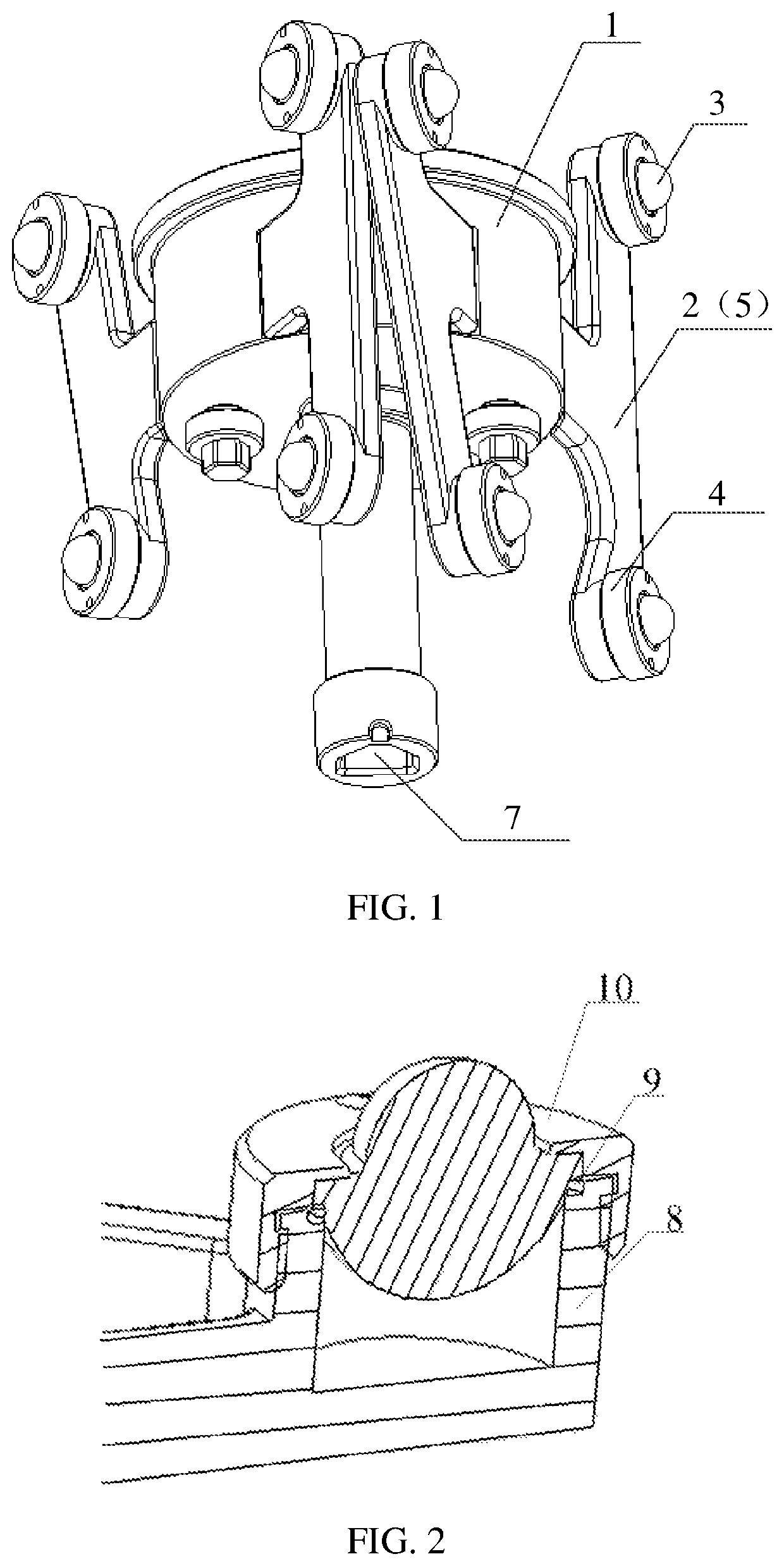
[0015]As shown in FIG. 1, this embodiment includes a mounting base 1 configured to be connected with an instrument at a tail end or a front end of the robot; two supporting faces 2 are arranged on the mounting base 1, four reflective balls 3 are mounted on each of the supporting faces 2, and each of the reflective balls 3 is fixed on the corresponding supporting face 2 through a reflective ball mounting base 4. In this embodiment, a positioning face 5 is formed by a quadrilateral with the four reflective balls 3 on the same supporting face 2 as end points. The included angle between the surface normal vectors of the two adjacent positioning faces 5 is 90°-140°, and the two positioning faces 5 are different in shape or size.

[0016]As shown in FIG. 2, the reflective ball mounting base 4 includes a ball support 8, a seal rubber ring 9 and an annular cover plate 10, wherein the ball support 8 is fixedly connected to the supporting face 2. In this embodiment, each of the reflective balls ...

embodiment 2

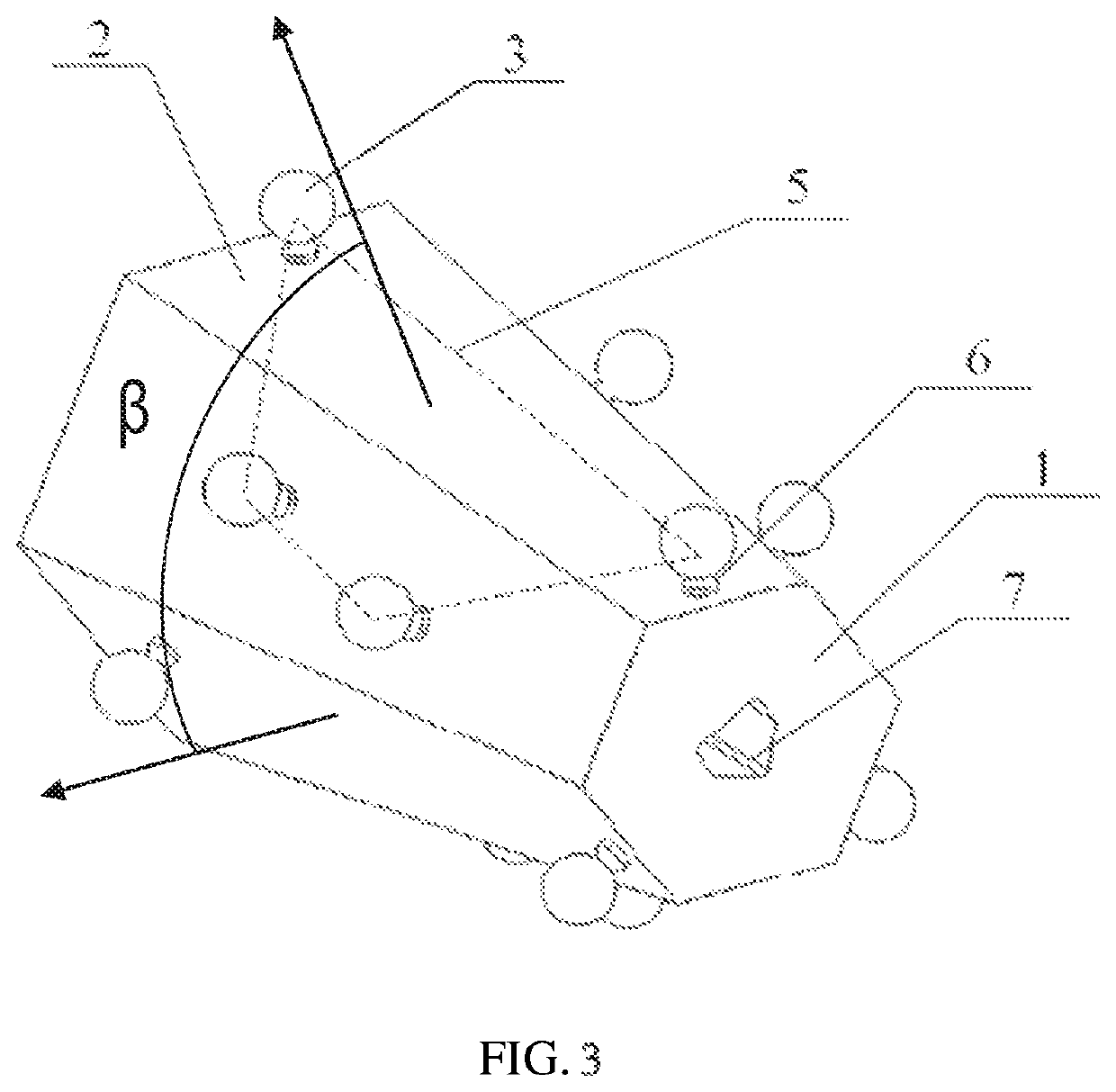
[0017]As shown in FIG. 3, this embodiment includes a mounting base 1 used to be connected with an instrument at a tail end or a front end of the robot; six supporting faces 2 are arranged on the mounting base 1, two reflective balls 3 are mounted on each of the supporting faces 2, each of the reflective balls 3 is connected to a corresponding supporting face 2 through a mounting column 6. In this embodiment, a positioning face 5 is formed by a quadrilateral with the four reflective balls 3 on the two adjacent supporting faces 2 as end points. The included angle β between the surface normal vectors of the two adjacent positioning faces 5 is 90°-140°, and any two positioning faces 5 are different in shape or size.

[0018]In each of the above two embodiments, the mounting base 1 is provided with an interface 7 to be connected with a surgical tool and / or a surgical robot.

[0019]Based on the above embodiments, the present invention further includes variations of the above embodiments. For e...


PUM


Abstract

Provided is an optical tracking tool for navigating a surgery, comprising a mounting base. The mounting base is provided with two to six supporting faces thereon. Two or four reflective balls are arranged on each of the supporting faces. A positioning surface is formed by the four reflective balls located on the same supporting face or the four reflective balls respectively located on two adjacent supporting faces. An included angle between surface normal vectors of two adjacent positioning surfaces is 90°-140°. As compared with a tracking tool having a single positioning surface formed by four reflective balls in the prior art, the optical tracking tool can considerably broaden an effective tracking range of a system, thereby improving system accuracy.

Description

CROSS-REFERENCE TO RELATED APPLICATIONS[0001]The present application is a U.S. National Phase of International Patent Application Serial No. PCT / CN2016 / 096661, entitled “OPTICAL TRACKING TOOL FOR NAVIGATING SURGERY,” filed on Aug. 25, 2016. International Patent Application Serial No. PCT / CN2016 / 096661 claims priority to Chinese Patent Application No. 201510547376.9, filed on Aug. 31, 2015. The entire contents of each of the above-cited applications are hereby incorporated by reference in their entirety for all purposes.TECHNICAL FIELD[0002]The present invention relates to an optical tracking tool for navigating a surgery, belonging to the technical field of computer-aided surgery.RELATED PRIOR ART[0003]Currently, the optical tracking device used clinically for navigating a surgery is mainly an optical positioning and tracking system manufactured by NDI Company of Canada. The positioning principle of this type of system is that: infrared light emitted by a binocular position sensor r...

Claims


Application Information

Patent Timeline
Patent Type & Authority Patents(United States)
IPC IPC(8): A61B34/20A61B34/30A61B90/00A61B34/00
CPCA61B34/20A61B34/30A61B90/39A61B34/25A61B2034/2055A61B2090/3983
Inventor XU, JINFENG, YUN
Owner BEIJING TINAVI MEDICAL TECH
Why Eureka
Try Eureka