Optical coherence tomographic device and light source

a coherence tomographic and optical coherence technology, applied in the field of optical coherence tomographic devices and light sources, can solve the problems of difficult measurement of the position of the retina, difficult detection of reflected light from the retina, and small so as to achieve the effect of increasing the amount of light reaching the retina

Active Publication Date: 2021-02-23
TOMEY CORP
View PDF13 Cites 1 Cited by
  • Summary
  • Abstract
  • Description
  • Claims
  • Application Information

AI Technical Summary

Benefits of technology

[0006]In the above optical coherence tomographic device, signal reception sensitivity can be increased by irradiating the subjected eye with light that satisfies the above-mentioned condition. Due to this, a signal of reflected light from a retina can be obtained with high sensitivity.
[0008]The above light source can adjust at least one of the wavelength swept frequency S and the center wavelength λ so as to irradiate the subjected eye with light that satisfies the above-mentioned condition. Due to this, the light source can bring similar operation and effect to those of the above optical coherence tomographic device.
[0010]In the other optical coherence tomographic device above, an amount of light reaching a retina can be increased since the diameter D of the light outputted from the light source at the incident position to the subjected eye is 3 mm or more. Due to this, even when a crystalline lens of the subjected eye has an opacified portion, a signal of reflected light from the retina can be obtained.

Problems solved by technology

However, if a crystalline lens of the subjected eye has an opacified portion, for example, due to cataract, the light outputted from a light source to the subjected eye may attenuate at the opacified portion, and an amount of light reaching a retina may become small.
As a result, it has been problematic that detection of reflected light from the retina is difficult and thus measurement for a position of the retina, an axial length and the like is difficult.

Method used


Image

  • Optical coherence tomographic device and light source
  • Optical coherence tomographic device and light source
  • Optical coherence tomographic device and light source

Examples


embodiment

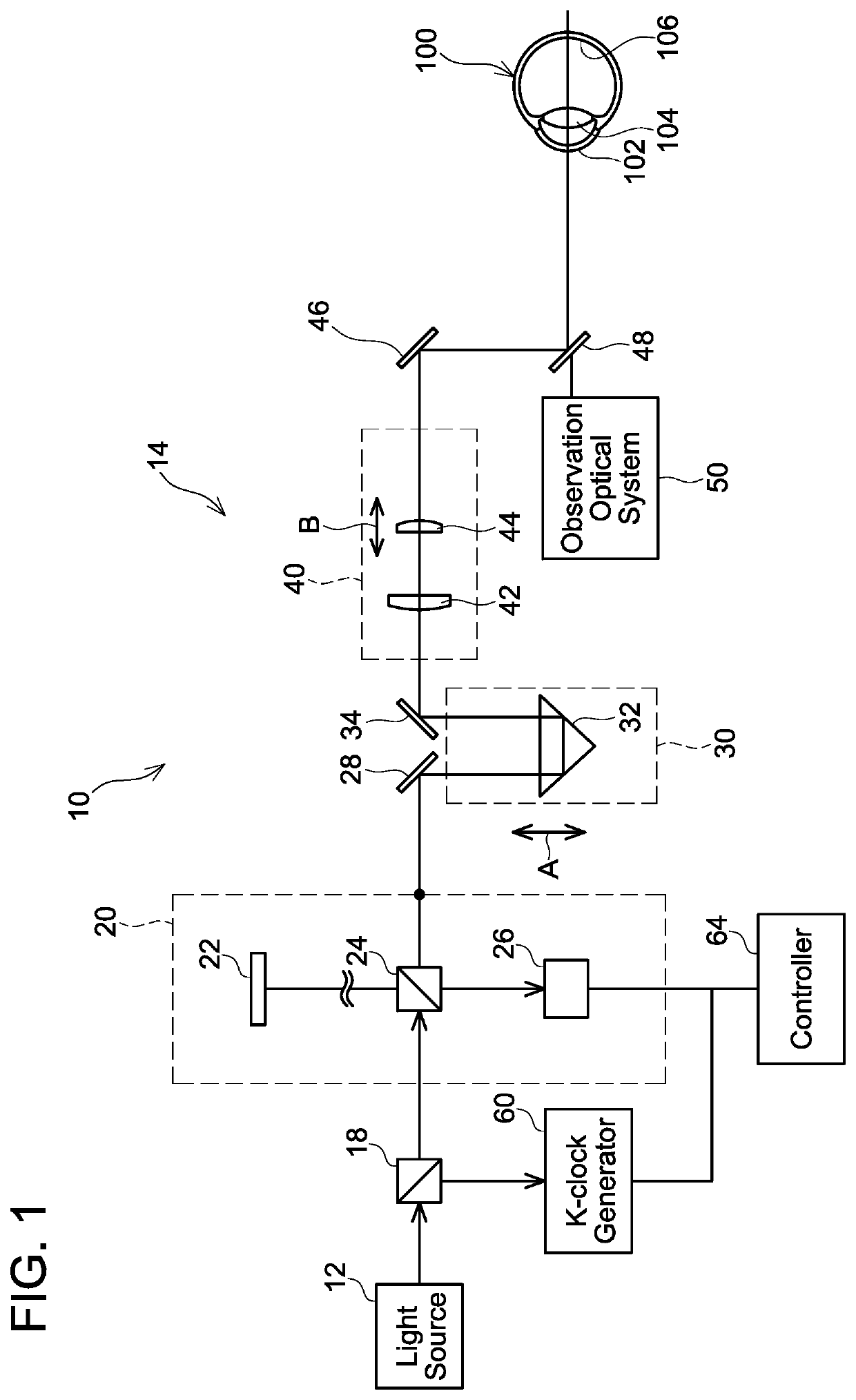
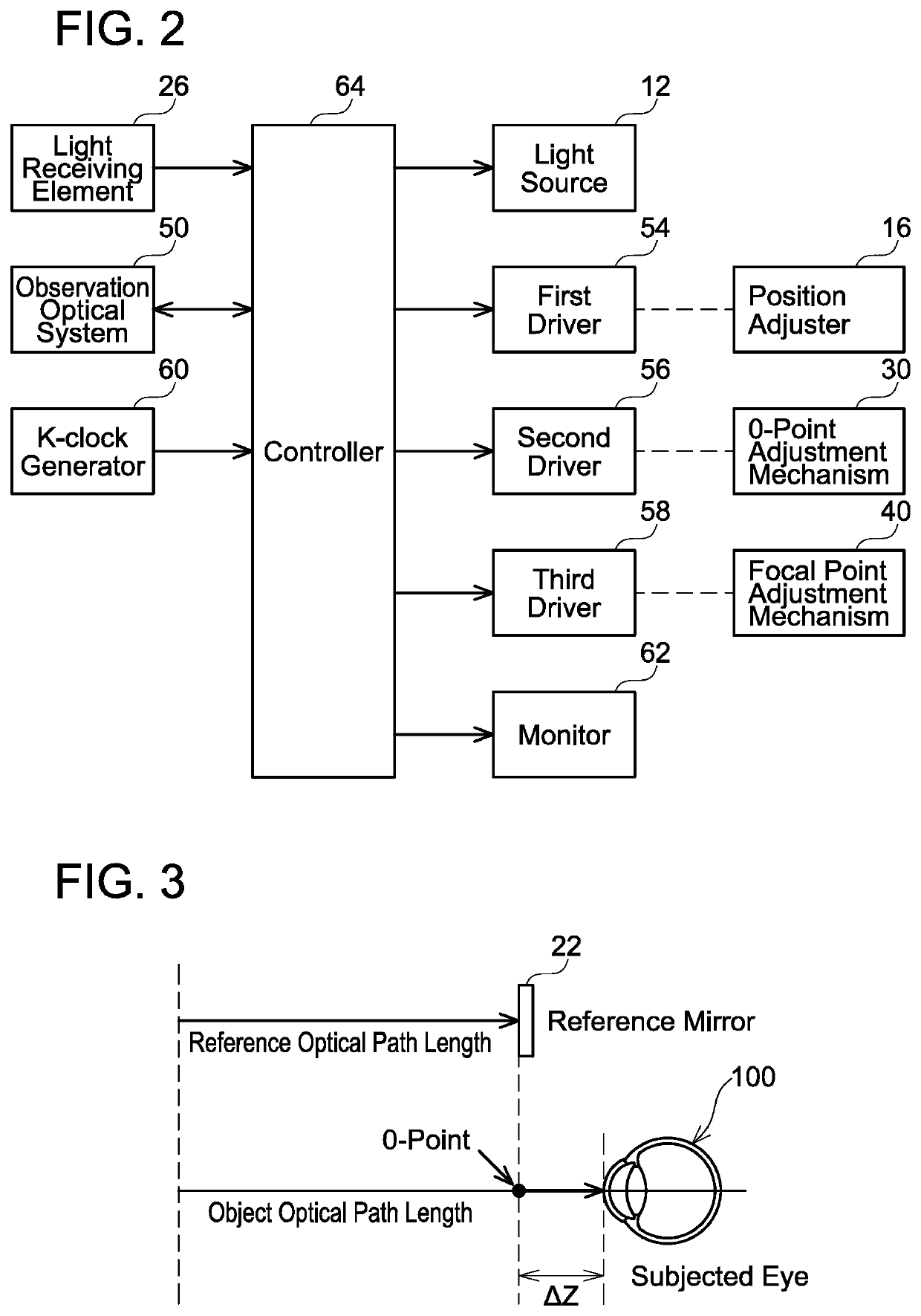
[0028]An optical coherence tomographic device of an embodiment will be described hereinbelow. As shown in FIG. 1, the optical coherence tomographic device comprises a light source 12, a measurement unit 10 configured to examine a subjected eye 100, and a K-clock generator 60. Light outputted from the light source 12 enters a beam splitter 18 and is split into light to be guided to the measurement unit 10 and light to be guided to the K-clock generator 60 in the beam splitter 18.

[0029]The measurement unit 10 comprises an interference optical system 14 configured to cause reference light interfere with reflected light that is reflected from the subjected eye 100, an observation optical system 50 configured to observe an anterior part of the eye 100, and an alignment optical system (not shown) configured to align the measurement unit 10 with respect to the subjected eye 100 in a predetermined positional relationship. An alignment optical system that has been used in a well-known optica...


PUM


Abstract

An optical coherence tomographic device configured to acquire a tomographic image of a subjected eye is disclosed herein. The optical coherence tomographic device may include a light source of wavelength sweeping type; and a measurement optical system configured to irradiate the subjected eye with light outputted from the light source, where D / S×λ>1.61 may be satisfied, with a diameter of the light outputted from the light source at an incident position to the subjected eye is D, a wavelength swept frequency of the light source is S, and a center wavelength of the light outputted from the light source is λ.

Description

CROSS-REFERENCE[0001]This application claims priority to Japanese Patent Application No. 2017-246663, filed on Dec. 22, 2017, the entire contents of which are incorporated herein by reference.TECHNICAL FIELD[0002]The technique disclosed herein relates to an optical coherence tomographic device and a light source used for the same.BACKGROUND ART[0003]Optical coherence tomographic devices configured to measure an axial length of a subjected eye and positions of parts in the subjected eye have been developed. For example, an optical coherence tomographic device of Japanese Patent Application Publication No. 2017-176842 is provided with a measurement optical system configured to irradiate a subjected eye with light outputted from a light source and guide reflected light from the subjected eye, and a reference optical system configured to irradiate a reference surface with the light outputted from the light source and guide reflected light from the reference surface. In measurement, a po...

Claims


Application Information

Patent Timeline
Patent Type & Authority Patents(United States)
IPC IPC(8): A61B3/10A61B3/00
CPCA61B3/102A61B3/0008A61B3/1225A61B3/14
Inventor NOZAWA, YUJIKATO, CHIHIROKAMO, TAKASHI
Owner TOMEY CORP
Why Eureka
Try Eureka