Optical module
a technology of optical modules and connecting parts, applied in semiconductor lasers, printed circuit non-printed electric components association, instruments, etc., can solve the problems of adverse effect on the reliability of optical modules themselves, significant degrading of high-frequency transmission characteristics, and impedance mismatch at connecting portions
- Summary
- Abstract
- Description
- Claims
- Application Information
AI Technical Summary
Benefits of technology
Problems solved by technology
Method used
Image


Examples
first embodiment
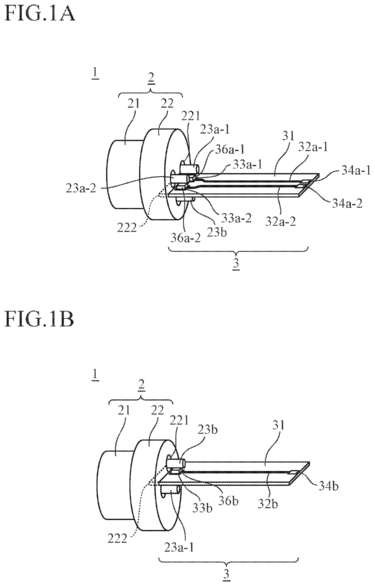
[0030]FIG. 1 is a diagram showing an exemplary configuration of an optical module 1 according to a first embodiment of the invention.
[0031]The optical module 1 transmits and receives optical signals. The optical module 1 includes, as shown in FIG. 1, a CAN package 2 and a board 3.
[0032]The CAN package 2 has, as shown in FIG. 2, a lens housing 21, a stem 22, and lead pins 23a and 23b.
[0033]The lens housing 21 includes therein a board (not shown) having an LD chip mounted thereon, etc.
[0034]The stem 22 is a heat dissipating member that dissipates heat from the lens housing 21. In addition, the stem 22 also functions as a ground conductor of the CAN package 2. The stem 22 is provided with through-holes 221 in an axial direction. In an example of FIG. 2, three through-holes 221 are provided.
[0035]The lead pins (first lead pins) 23a are lead pins that transmit electrical signals, and one end of each lead pin 23a is electrically connected to the board included in the lens housing 21 thro...
second embodiment
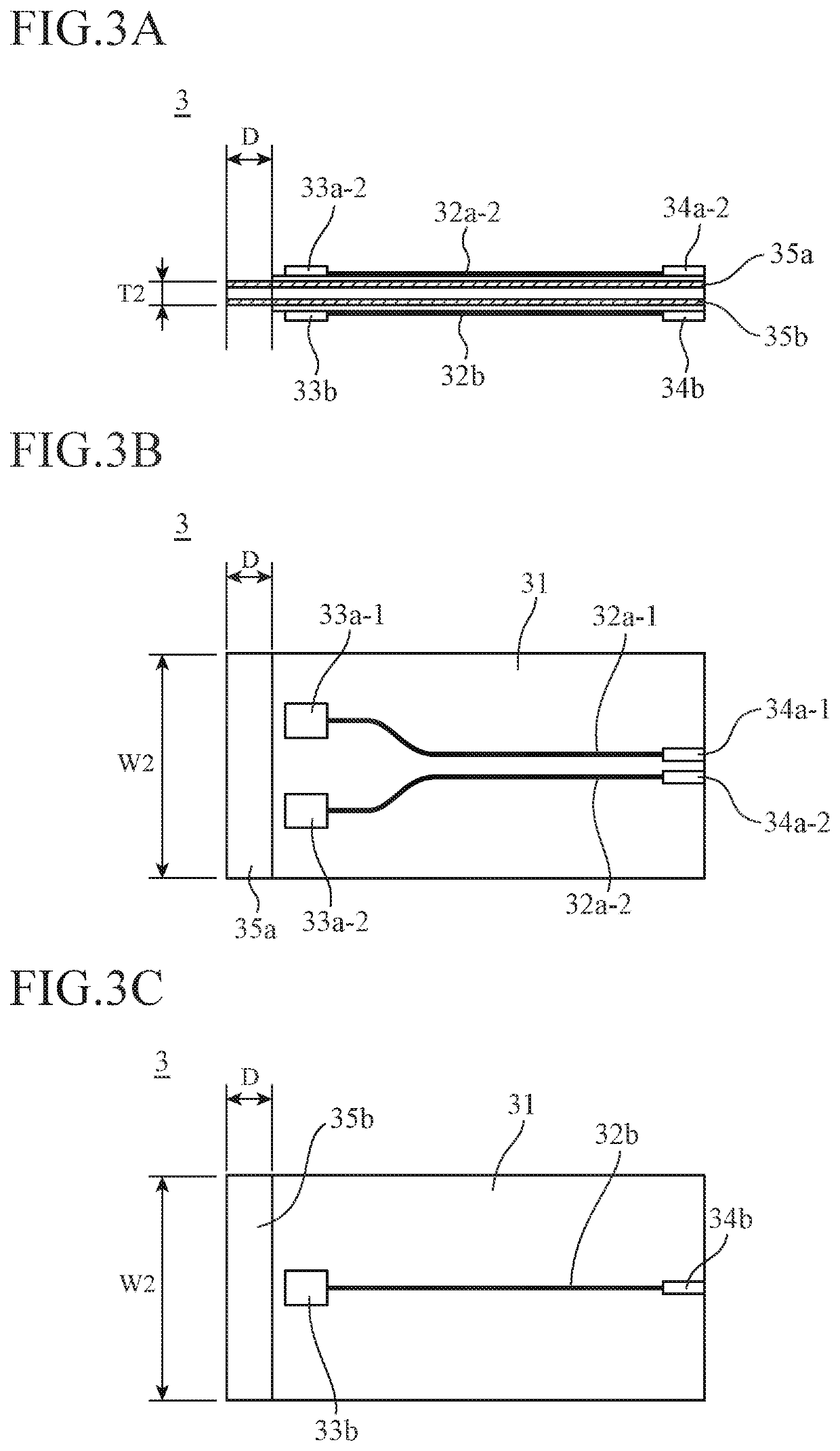
[0067]The first embodiment shows a case in which after inserting the board 3 into the slot 222, the board 3 is fixed to the CAN package 2 by soldering, etc. On the other hand, a second embodiment shows a case in which the board 3 is fixed to the CAN package 2 by inserting and fitting the board 3 into the slot 222.
[0068]Here, a dimensional relationship between the slot 222 and the one end of the board 3 is formed so as to satisfy at least the following relational inequality (3) or relational inequality (4). In inequalities (3) and (4), T1′ is the thickness of at least a part of the slot 222, and W1′ is the width of at least a part of the slot 222.
T1′
W1′
[0069]By satisfying the inequality (3) or (4), when the board 3 is inserted into the slot 222, the stem 22 clamps the board 3, thus enabling an electrical connection. Specific examples are shown in FIGS. 8 to 10 below. Note that in FIGS. 8 to 10 depiction of the lead pins 23a and 23b and the through-holes 221 is omitted...
third embodiment
[0075]The first embodiment shows a case in which the lead pins 23a are connected to the pads 33a for connecting lead pin through the conductors 36a. On the other hand, a third embodiment shows a case in which the lead pins 23a are connected to the pads 33a for connecting lead pin by direct contact therebetween.
[0076]FIG. 11 is a diagram showing an exemplary configuration of an optical module 1 according to the third embodiment of the invention. The optical module 1 according to the third embodiment which is shown in this FIG. 11 has the slot 222 at a different position and has no conductors 36a as compared with the optical module 1 according to the first embodiment which is shown in FIG. 1. In addition, the jumper wire 38 is used instead of the conductor 36b. Other configurations are the same and denoted by the same reference signs and description thereof is omitted.
[0077]The slot 222 is offset toward the side of the lead pins 23a, i.e., provided near the lead pins 23a. In FIG. 12, ...
PUM
 Abstract
Description
Claims
Application Information
 - R&D
- Intellectual Property
- Life Sciences
- Materials
- Tech Scout
- Unparalleled Data Quality
- Higher Quality Content
- 60% Fewer Hallucinations
Browse by: Latest US Patents, China's latest patents, Technical Efficacy Thesaurus, Application Domain, Technology Topic, Popular Technical Reports.
© 2025 PatSnap. All rights reserved.Legal|Privacy policy|Modern Slavery Act Transparency Statement|Sitemap|About US| Contact US: help@patsnap.com