Box coating apparatus for vacuum coating of substrates, in particular spectacle lenses

a technology of vacuum coating and substrate, applied in the field of box coating apparatus, can solve the problem of not optimizing the pumping speed to maximize the speed, and achieve the effect of low complexity and expenditur

Active Publication Date: 2021-02-09
SATISLOH AG
View PDF81 Cites 0 Cited by
  • Summary
  • Abstract
  • Description
  • Claims
  • Application Information

AI Technical Summary

Benefits of technology

[0017]In other words, the basic idea of the present invention is to cover or shield one or more of the functional components of the box coating apparatus other than the evaporation source and the substrate holder, including at least the Meissner trap and / or the high vacuum valve mechanism, i.e. the functional components comprised in the pumping system of the box coating apparatus that are sensitive to thin film depositions, with an “intelligent mask system” that can be open or close depending on the process phase. During the pumping down phase the shutter portion of the shield arrangement can be kept completely open, i.e. remain in the open pumping position with a substantially cleared passageway for gases and vapor through the shield arrangement, thereby maximizing the conductance towards the pumping arrangement and therefore also increasing the speed of the pumping arrangement. This gives benefits in reducing the pumping down time and increasing therefore the productivity of the box coating apparatus. Otherwise, when the deposition process is on, there is no need for having high values of pumping speed. In this case the shutter portion of the shield arrangement can be kept close, i.e. remain in the closed shielding position, so that the passageway leading through the shield arrangement is blocked and the respective sensitive functional component behind the shield arrangement is not covered with thin films. This increases again the productivity of the box coating apparatus by reducing maintenance time (no need to clean the functional components from the deposited thin films) and increasing the duty cycle. Another benefit is related to a reduced consumption of process gases which are injected during some deposition steps, because of the reduced conductance and pumping speed obtained by closing the shutter portion of the shield arrangement.
[0031]Finally, and again with a view to low complexity and expenditure, preferably the arrangement can be such that the actuator is operatively connected to the above described connecting piece in order to simultaneously pivot the slat elements by one and the same actuator. Generally, this concept can be used where two or more shutter or slat elements are to be moved at the same time and in the same linear direction or sense of rotation, as the case may be.

Problems solved by technology

This of course helps in preventing any deposition on the two sensitive functional components but is not an optimized solution that maximizes pumping speed during the pumping down phase.

Method used


Image

  • Box coating apparatus for vacuum coating of substrates, in particular spectacle lenses
  • Box coating apparatus for vacuum coating of substrates, in particular spectacle lenses
  • Box coating apparatus for vacuum coating of substrates, in particular spectacle lenses

Examples


Embodiment Construction

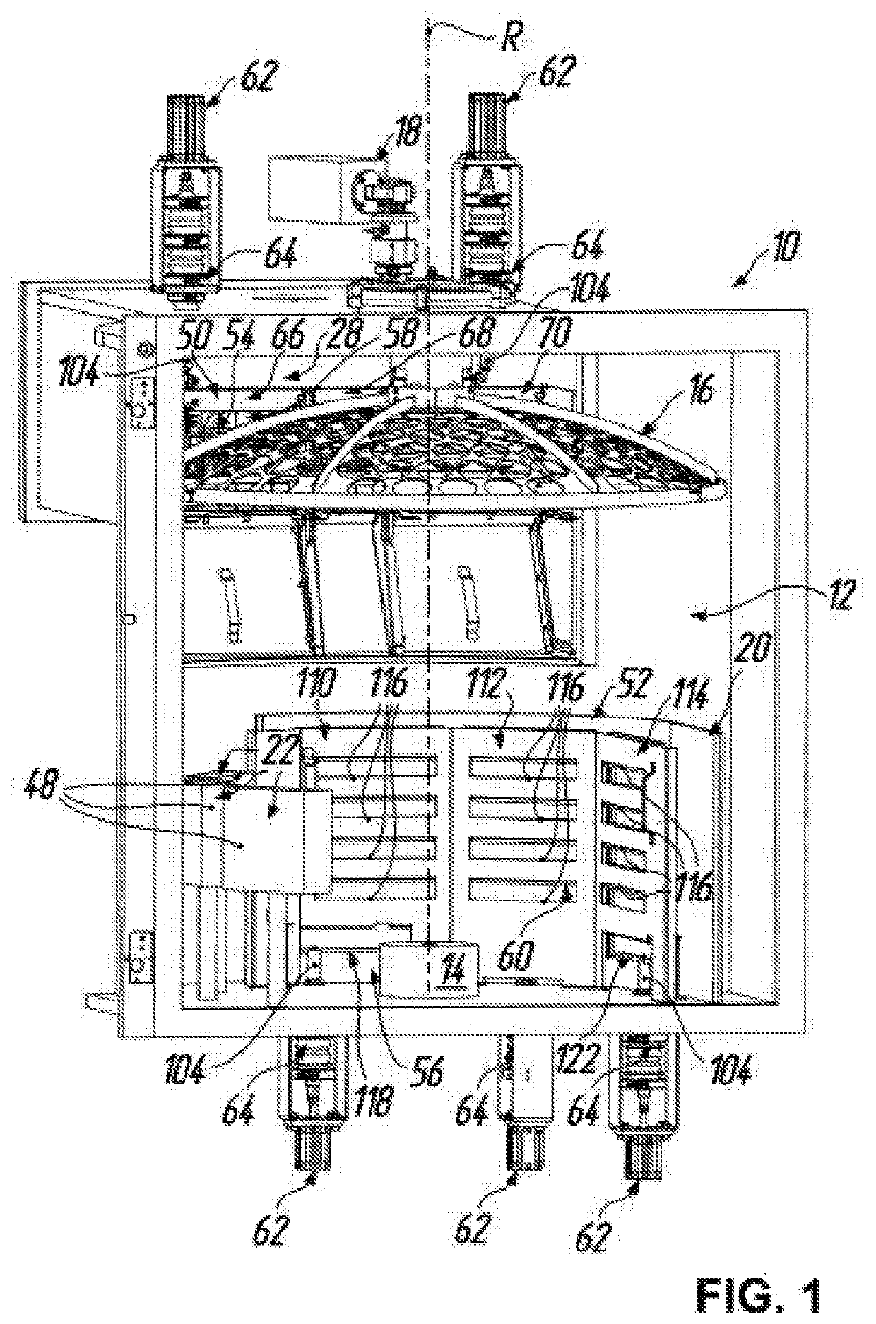
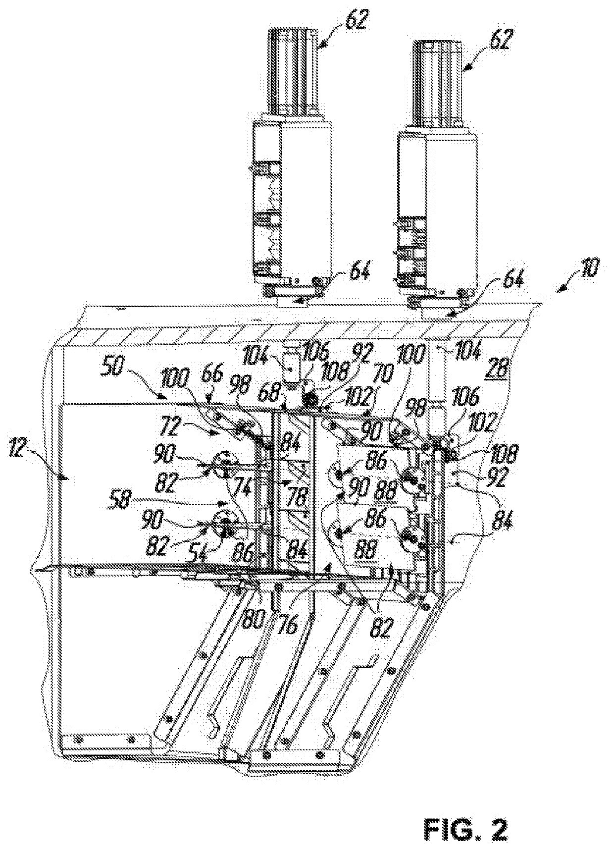
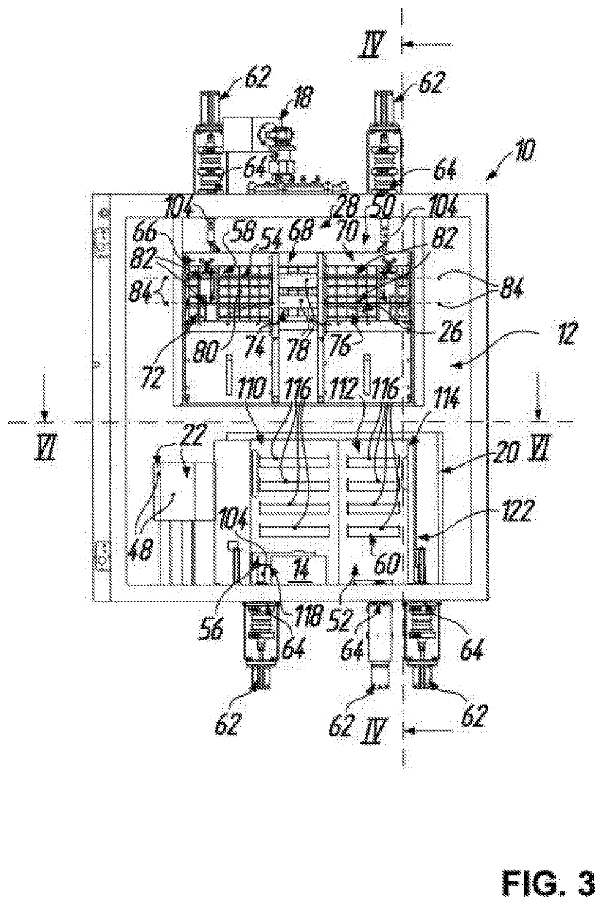
[0047]A box coating apparatus for vacuum coating of substrates (not shown in the drawings), particularly spectacle lenses, is denoted by 10 in FIGS. 1 to 8. As indicated before, such box coating apparatus 10 generally has a vacuum chamber 12 which can be evacuated by a pumping arrangement in a manner known per se (cf. FIG. 14 at 25). The vacuum chamber 12 contains an evaporation source 14 for evaporating coating material. A substrate holder 16 for holding a plurality of substrates is disposed vis-à-vis to the evaporation source 14 in the vacuum chamber 12 so that the coating material evaporated by the evaporation source 14 can impinge on substrates held by the substrate holder 16.

[0048]Besides the evaporation source 14 and the substrate holder 16 various functional components are provided in or adjacent to the vacuum chamber 12. These functional components include at least a Meissner trap 20 and a high vacuum valve mechanism 26 (cf. FIGS. 3 and 14). As further functional components ...


PUM

PropertyMeasurementUnit
temperatureaaaaaaaaaa
pressuresaaaaaaaaaa
vacuum pressureaaaaaaaaaa

Abstract

A box coating apparatus for coating of substrates comprises a vacuum chamber which contains an evaporation source. A substrate holder is disposed vis-à-vis to the evaporation source so that evaporated material can impinge on substrates held by the substrate holder. Besides the evaporation source and the substrate holder, at least one further functional component is provided, namely a Meissner trap and / or a high vacuum valve mechanism, to which a shield arrangement is assigned to prevent evaporated material from impinging on said component. This shield arrangement has a shutter portion which can be moved from a closed shielding position in which it covers a passageway through the shield arrangement and serves to shield said component, to an open pumping position in which it substantially clears the passageway to allow essentially free passage for gases and vapor, and vice versa.

Description

TECHNICAL FIELD OF THE INVENTION[0001]The present invention generally relates to a box coating apparatus for vacuum coating of substrates. Such apparatus generally serves the purpose of high vacuum deposition of multilayer thin films on substrates of various materials, both organic and inorganic, usually used in optical applications. In particular, the present invention relates to a box coating apparatus for vacuum coating of spectacle lenses, which has useful application for large-scale production of spectacle lenses. In this case, typically, the box coating apparatus serves the purpose of applying a multilayer antireflection (AR) coating on the spectacle lenses in order to provide the latter with a low residual reflection and a desired color. It can however also be used for other coating purposes, e.g., for applying on top of such AR coating a top coating (TC) selected from a group comprising hydrophobic, oleophobic and dust repelling coatings.BACKGROUND OF THE INVENTION[0002]The ...

Claims


Application Information

Patent Timeline
Patent Type & Authority Patents(United States)
IPC IPC(8): C23C16/56C23C14/56C23C14/24C23C14/06C23C14/52
CPCC23C14/564C23C14/0635C23C14/24C23C14/52C23C14/042C23C14/54B29D11/00865C23C14/50C23C14/04G02C7/02
Inventor DI PAOLA, GIUSEPPEMORENI, FRANCOCOREA, ANTONIOVISCOMI, GIUSEPPEBREME, FRANK
Owner SATISLOH AG
Why Eureka
Try Eureka