Alternator control unit, alternator driving control method, and power supply management system for engine vehicle
a technology of power supply management system and control unit, which is applied in the direction of electric generator control, machines/engines, transportation and packaging, etc., can solve the problems of consuming a part of engine output, reduce engine efficiency, suppress the drive of the alternator, etc., and achieve low engine efficiency. , the effect of reducing engine efficiency
- Summary
- Abstract
- Description
- Claims
- Application Information
AI Technical Summary
Benefits of technology
Problems solved by technology
Method used
Image

Examples
first embodiment
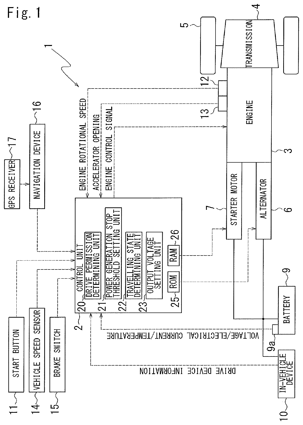
Relating to a Drive Control of the Alternator 6
[0053]Next, an explanation will be made of a drive control of the alternator 6 by the control unit 2.
[0054]The control unit 2 is provided with a drive, permission determining unit 20. The drive permission determining unit 20 determines whether to perform a drive of the alternator 6 based upon a traveling state (deceleration or not) of a vehicle, an SOC of the battery 9, an engine efficiency, a load (power consumption) state and the like.
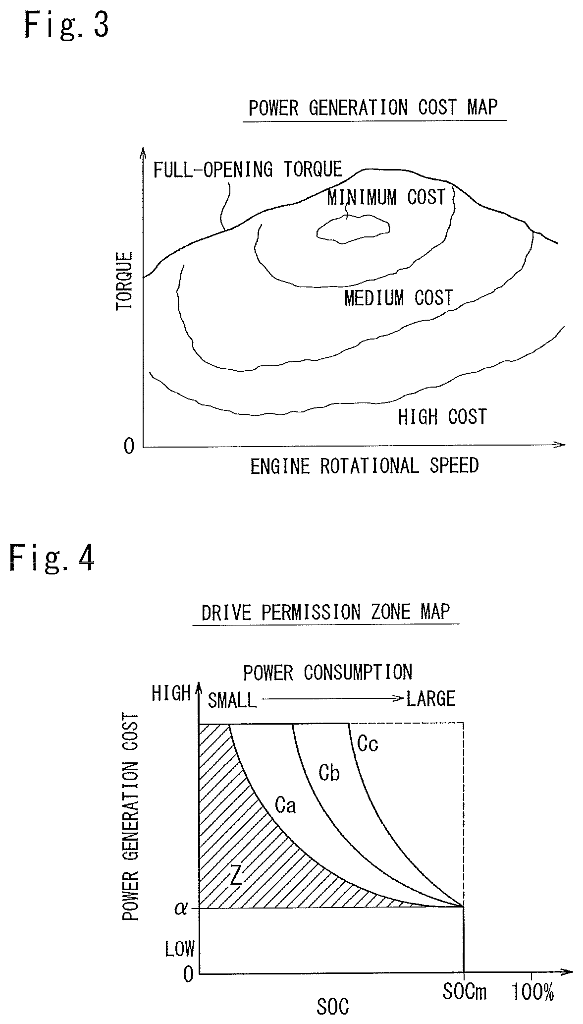
[0055]Here, the control unit 2 uses, as an index of the engine, efficiency, a power generation cost map M1 (refer to FIG. 3) stored in a ROM 25.
[0056]The power generation cost map M1 defines a power generation cost (yen / KWh) of the alternator 6 to an engine rotational speed and torque outputted from the engine 3, based upon a fuel consumption quantity.
[0057]As a general trend, the cost is relatively lower in a medium speed region in the vehicle driving speed than in the other regions (high speed region a...
second embodiment
Relating to a Drive Control of the Alternator 6
[0132]Hereinafter, an explanation will be made of a second embodiment relating to a drive control of the alternator 6.
[0133]FIGS. 5A and 5B is graphs illustrating a relation between a WGI (wasteful power generation index) and a drive permission upper limit line C. FIG. 5A is a graph explaining a relation between the WGI, the SOC and the power generation cost. FIG. 5B is a graph indicative of drive permission upper limit lines Ca to Cc determined corresponding to thresholds (WGI_a to WGI_c) set by the WGI.
[0134]FIGS. 6A and 6B is graphs explaining a threshold (power generation stop threshold SOCs) for stopping power generation by the alternator 6. FIG. 6A is a graph explaining a relation between the power generation stop threshold SOCs and the drive permission zone map M2 illustrated in FIG. 4. FIG. 6B is a schematically-illustrated drive permission zone map. This drive permission zone map shows a part of the drive permission zone map il...
modification 1
[0210][Modification 1]
[0211]In the second embodiment, a case where the power generation stop threshold SOCs is changed according to the travelling state of the vehicle is exemplified. But the threshold WGI_TH in the WGI (wasteful power generation index: refer to FIG. 5(a)) may include a plurality of thresholds (WGI_a to WGI_c) that are preliminarily set to prepare for a plurality of drive permission upper limit lines C (Ca to Cc). In this case, it may be possible to change the drive permission upper limit line C according to the traveling state of the vehicle by changing from among a plurality of drive permission upper limit lines C (Ca to Cc).
[0212]FIG. 9 is a graph explaining the plurality of drive permission upper limit lines C (Ca to Cc) and the power generation stop threshold SOCs. Each of the drive permission upper limit line C (Ca to Cc) is obtained when setting the threshold WGI_TH in the WGI to the plurality of thresholds (WGI_a to WGI_c).
[0213]In the above-mentioned second...
PUM
 Abstract
Description
Claims
Application Information
 - R&D
- Intellectual Property
- Life Sciences
- Materials
- Tech Scout
- Unparalleled Data Quality
- Higher Quality Content
- 60% Fewer Hallucinations
Browse by: Latest US Patents, China's latest patents, Technical Efficacy Thesaurus, Application Domain, Technology Topic, Popular Technical Reports.
© 2025 PatSnap. All rights reserved.Legal|Privacy policy|Modern Slavery Act Transparency Statement|Sitemap|About US| Contact US: help@patsnap.com