Power conversion device

a power conversion device and power conversion technology, applied in the direction of transformer/inductance details, transformer/inductance coil/winding/connection, transformer/inductance cooling, etc., can solve the problems of marked increase in heat loss due to heat loss frequency of core materials, and increase in core temperature markedly, so as to achieve stably driven, power conversion device driven, and increase the effect of core heat dissipation

Active Publication Date: 2021-11-02
MITSUBISHI ELECTRIC CORP
View PDF13 Cites 0 Cited by
  • Summary
  • Abstract
  • Description
  • Claims
  • Application Information

AI Technical Summary

Benefits of technology

[0014]According to a power conversion device of the invention, an electromagnetic induction instrument is fixed to a frame body by a fixing member, whereby upper and lower cores separating at a core abutment interface, and an inductance value decreasing, due to thermal expansion of a potting resin member caused by a rise in temperature when the power conversion device is driven can be restricted, and the power conversion device can be stably driven. Also, a power conversion device such that vibration resistance of the electromagnetic induction instrument can be secured, even when the power conversion device is exposed to vibration and impact conditions when the vehicle is travelling, can be provided. Also, by filling with the potting resin member and connecting to the frame body, core heat dissipation can be increased, and a reduction in size, a reduction in weight, and a reduction in cost of the power conversion device can be realized.

Problems solved by technology

Due to increasing the frequency in order to reduce size, there is a marked increase in heat loss due to core material heat loss frequency characteristics, particularly when adopting a method whereby the core sectional area is reduced.
Furthermore, a problem exists in that a rise in core temperature increases markedly due to an increase in core thermal resistance caused by reducing the core sectional area.

Method used


Image

  • Power conversion device
  • Power conversion device
  • Power conversion device

Examples


first embodiment

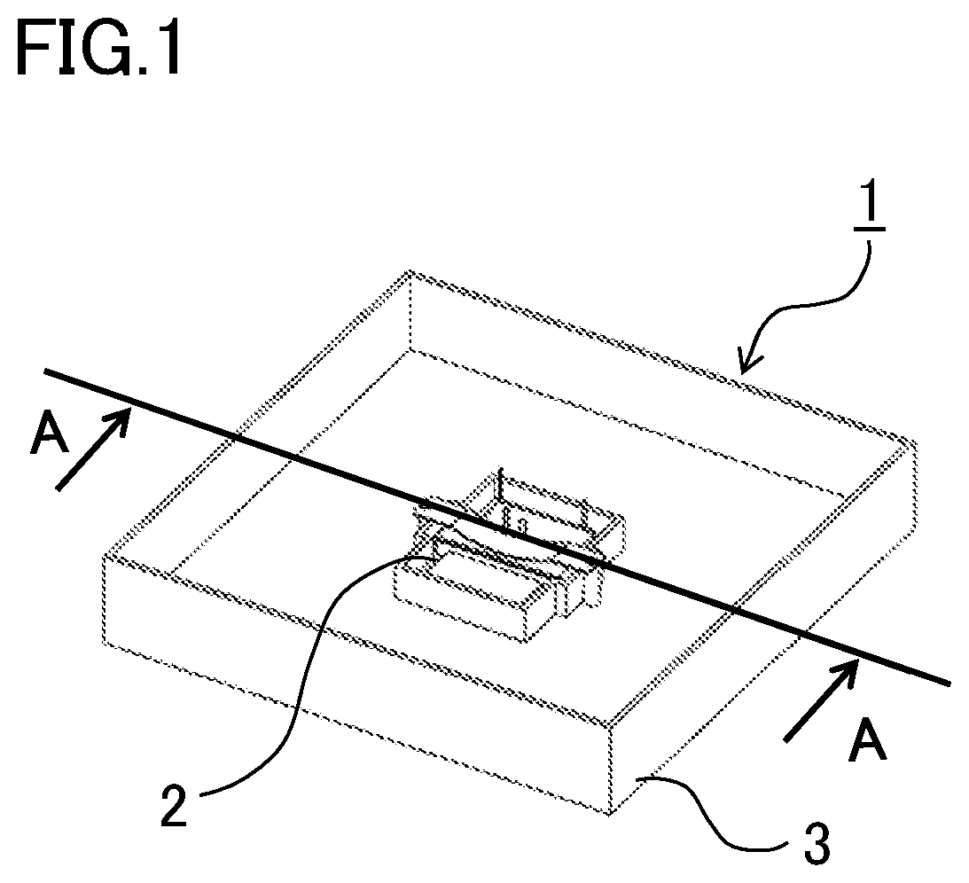
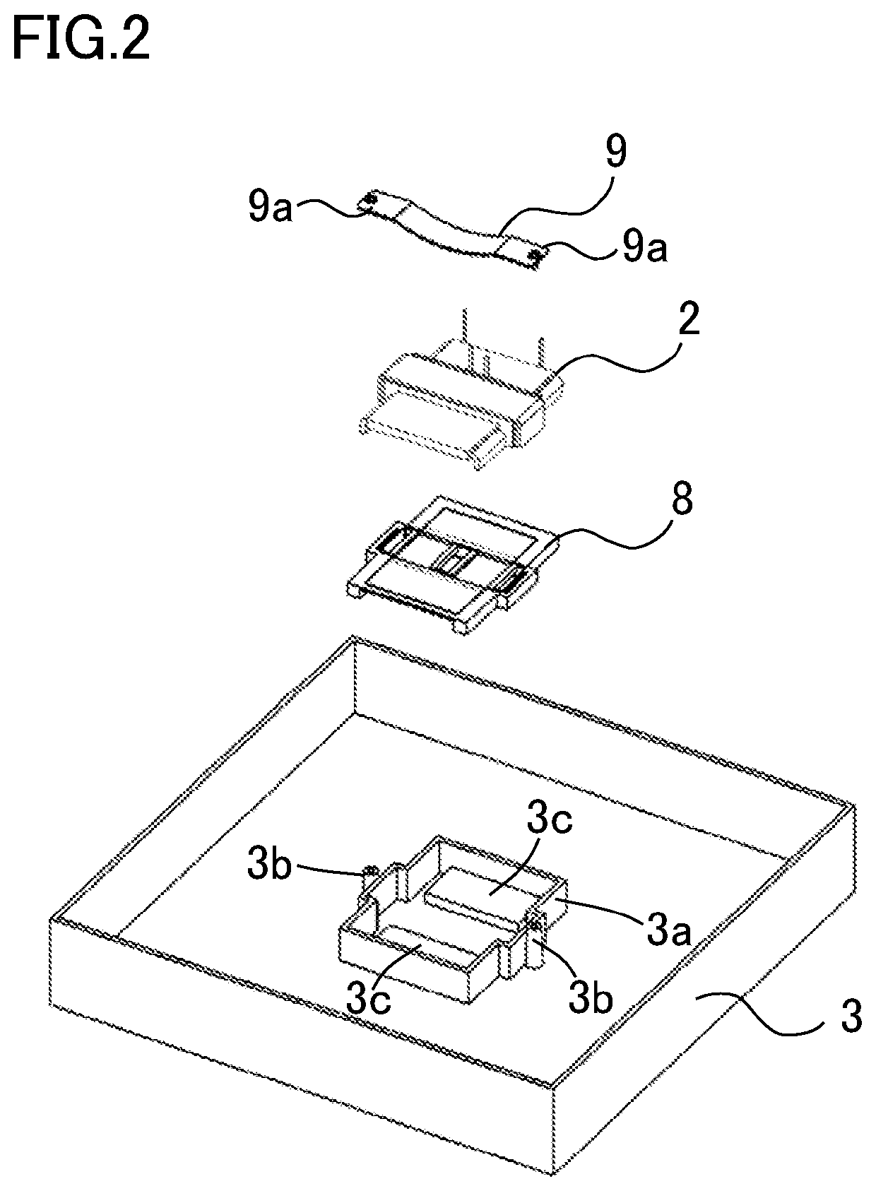
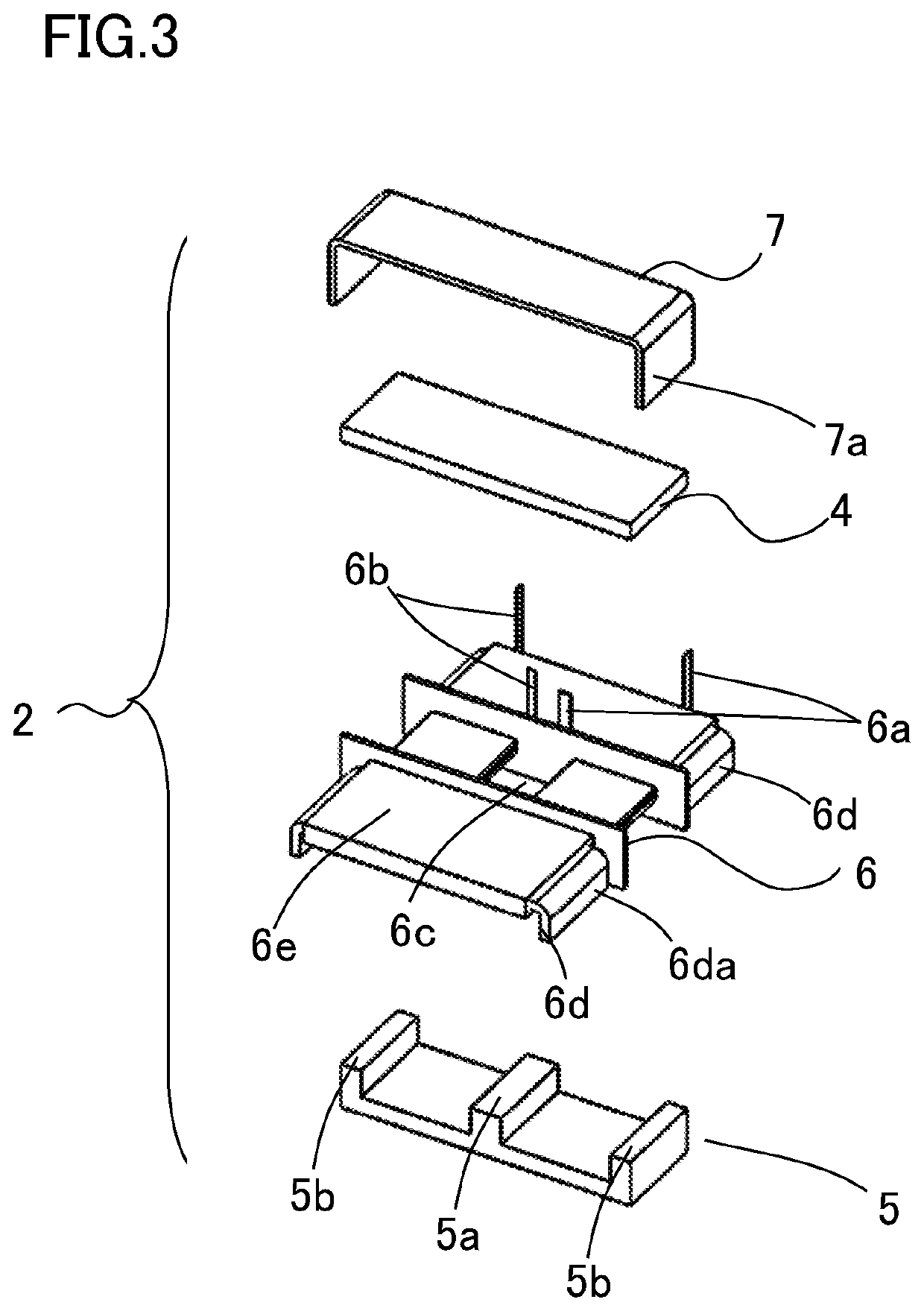
[0039]FIG. 1 is a perspective view showing a power conversion device in the first embodiment of the invention, and FIG. 2 is an exploded view of the power conversion device shown in FIG. 1. Also, FIG. 3 is an exploded view of an electromagnetic induction instrument mounted in the power conversion device of FIG. 1 and FIG. 2, and FIG. 4 is a primary winding configuring a coil body shown in FIG. 3. Further still, FIG. 5 is a secondary winding configuring the coil body shown in FIG. 3, and FIG. 6 is a sectional view showing a cross-section along an A-A line in the power conversion device shown in FIG. 1. A depiction of a substrate and other components mounted in the power conversion device is omitted from FIG. 1 and FIG. 6.

[0040]As shown in FIG. 1, a power conversion device 1 is configured by a transformer 2, which is an electromagnetic induction instrument, being mounted in a frame body 3, and the frame body 3 and a cover existing on a side opposite to that of the frame body 3 being j...

second embodiment

[0079]FIG. 12 is a perspective view showing a power conversion device according to a second embodiment of the invention, and FIG. 13 is a sectional view showing a cross-section along a C-C line in the power conversion device of FIG. 12. Also, FIG. 14 is a perspective view showing a fixing member configuring the power conversion device in FIG. 12 and FIG. 13. A substrate and other components mounted in the power conversion device are omitted from FIG. 12.

[0080]The power conversion device 1 in the second embodiment of the invention is such that the fixing member 9 fixing the transformer 2 is not in contact with the transformer 2, and the fixing member 9 is disposed above the transformer 2 across the potting resin member 8. Also, the power conversion device 1 according to the second embodiment of the invention is such that filling with the potting resin member 8 is carried out to a height such that the fixing member 9, including the transformer 2, is impregnated. In the second embodime...

third embodiment

[0089]FIG. 15 is a perspective view showing a power conversion device in a third embodiment of the invention, and FIG. 16 is a perspective view showing a transformer module configuring the power conversion device of FIG. 15. Also, FIG. 17 is an exploded view of the transformer module of FIG. 16, and FIG. 18 is a sectional view showing a cross-section along a D-D line in the power conversion device of FIG. 15. A substrate and other components mounted in the power conversion device are omitted from FIG. 15. The transformer 2 configuring the power conversion device of the third embodiment of the invention is housed in advance in a case 18, and configured as a transformer module 17 filled with the potting resin member 8, and the transformer module 17 is mounted on and fixed to the frame body 3.

[0090]As shown in FIG. 16 and FIG. 17, the transformer 2 is configured as the transformer module 17 by being housed in advance in the case 18, after which the case 18 is filled with the potting re...


PUM


Abstract

A power conversion device such that heat dissipation of an electromagnetic induction instrument can be increased, and inductance value durability and vibration resistance of the electromagnetic induction instrument is high, is provided. Also, a power conversion device reduced in size and weight is provided. A power conversion device includes an electromagnetic induction instrument wherein an upper core and a lower core having magnetism are electromagnetically coupled across a coil body, a frame body on which the electromagnetic induction instrument is mounted, a potting resin member with which a space between the frame body and the electromagnetic induction instrument is filled, and a fixing member, disposed above the electromagnetic induction instrument so as to cover the upper core, of which an end portion is attached to the frame body, wherein the electromagnetic induction instrument is fixed to the frame body by the fixing member.

Description

TECHNICAL FIELD[0001]The present invention, relating to a power conversion device, relates to, for example, a power conversion device such as an inverter, a DC / DC converter, or a vehicle-mounted charger configured of a transformer, a reactor, or the like, mounted in an electric vehicle or a hybrid vehicle that has a motor as one drive source.BACKGROUND ART[0002]A power conversion device such as a DC / DC converter or a vehicle-mounted charger mounted in an electric vehicle Or a hybrid vehicle is such that an electromagnetic induction instrument is mounted as a passive component that carries out a voltage step-up operation or step-down operation. The electromagnetic induction instrument is a transformer, a reactor, a choke coil, or the like, and is used for accumulating or discharging energy, or for smoothing a direct current, or the like. With regard to this kind of electromagnetic induction instrument, reducing size or adopting a structure such that heat generated when energizing can...

Claims


Application Information

Patent Timeline
Patent Type & Authority Patents(United States)
IPC IPC(8): H02M1/44H02M3/28
CPCH02M1/44H02M3/28H02M7/003H01F27/266H01F27/22H01F27/022H01F27/30H01F27/025H01F27/16H02M1/327H02M3/003
Inventor URYU, YUTA
Owner MITSUBISHI ELECTRIC CORP
Why Eureka
Try Eureka