Hydraulic control device for drive power distribution device

a technology of hydraulic control device and power distribution device, which is applied in the direction of mechanical equipment, transportation and packaging, tractors, etc., can solve the problem of likely overshoot problem, and achieve the effect of improving durability, high accuracy and reducing the frequency of use of the motor

Active Publication Date: 2018-08-28
HONDA MOTOR CO LTD
View PDF12 Cites 0 Cited by
  • Summary
  • Abstract
  • Description
  • Claims
  • Application Information

AI Technical Summary

Benefits of technology

[0011]The hydraulic control device according to the present invention employs the sealed-type hydraulic circuit as described above and stops drive of the oil pump by the motor after the piston chamber is pressurized to the commanded hydraulic pressure. The hydraulic pressure of the hydraulic fluid sealed in the fluid path can keep the fastening force of the clutch constant until the piston chamber starts to be depressurized. This allows the motor for driving the oil pump to intermittently operate while the engagement pressure of the clutch is being produced. The frequency of use of the motor is therefore reduced, thus improving the durability. On the other hand, to supply hydraulic pressure to the piston chamber in a predetermined low torque region, the hydraulic control device controls the hydraulic pressure according to the third characteristic, which is obtained by opening the on-off valve and driving the oil pump, so that the pressure of the piston chamber becomes the commanded hydraulic pressure (when the on-off valve is opened, the hydraulic control is non-sealed control that is, flow-rate control by the motor). This enables fine hydraulic control, providing highly accurate four-wheel-drive mode in the low torque transmission region for the auxiliary driving wheel. Moreover, the hydraulic control device performs control to limit the drive of the motor at least just before the transition from the third to first characteristic. This can prevent overshoot (exceeding the commanded hydraulic pressure) of the actual hydraulic pressure which can occur just after the transition to the first characteristic due to the motor's inertia at the transition.
[0012]In an embodiment, the controller may perform control so as to limit the drive of the motor in the region where the deviation between the commanded hydraulic pressure and actual hydraulic pressure in the piston chamber is small at the transition from the third to first characteristic. In the region where the deviation between the commanded hydraulic pressure and actual hydraulic pressure is small, the actual hydraulic pressure is close to the commanded hydraulic pressure. Accordingly, the overshoot problem is likely to occur even if the undesired increase in the actual hydraulic pressure is relatively slight. To the contrary, in the region where the deviation between the commanded hydraulic pressure and actual hydraulic pressure is large, the actual hydraulic pressure is quite different from the commanded hydraulic pressure, and some increase in the actual hydraulic pressure is less likely to create an overshoot problem. In such a case, it is preferable that the drive of the motor is not limited (or limited by a smaller degree) so that the actual hydraulic pressure easily follows the commanded hydraulic pressure. By selectively limiting drive of the motor depending on the magnitude of the hydraulic pressure deviation in such a manner, the overshoot problem of hydraulic pressure is solved efficiently.
[0013]In another embodiment, in the region where the deviation between the commanded hydraulic pressure and actual hydraulic pressure is small, the controller may perform control so that the smaller the deviation, the higher the ratio at which the drive of the motor is limited. This can prevent overshoot of the actual hydraulic pressure which can be caused by the inertia of the motor at the transition from the third to first characteristic without degrading the following performance during the hydraulic pressure control according to the third characteristic. In the region where the deviation of the commanded hydraulic pressure and the actual hydraulic pressure is small, the larger the deviation, the lower the ratio at which the drive of the motor is limited, so that the following performance of the hydraulic pressure control can be relatively improved.

Problems solved by technology

Accordingly, the overshoot problem is likely to occur even if the undesired increase in the actual hydraulic pressure is relatively slight.

Method used


Image

  • Hydraulic control device for drive power distribution device
  • Hydraulic control device for drive power distribution device
  • Hydraulic control device for drive power distribution device

Examples


Embodiment Construction

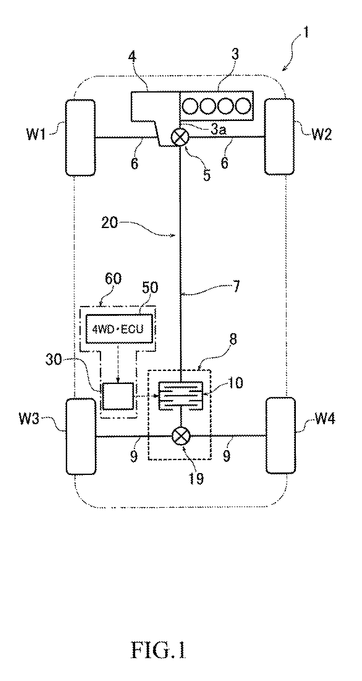
[0022]FIG. 1 is a diagram illustrating a schematic configuration of a four-wheel-drive vehicle including a hydraulic control device for a drive power distribution device according to an embodiment of the invention. A four-wheel-drive vehicle 1 illustrated in FIG. 1 includes: an engine (a drive source) 3 placed transversely in the front of the vehicle; an automatic transmission 4 integrally installed with the engine 3; and a drive power transmission path 20 configured to transmit drive power from the engine 3 to front wheels W1 and W1 and rear wheels W3 and W4.

[0023]The output shaft (not illustrated) of the engine 3 is coupled to the left and right front wheels W1 and W2 as main driving wheels through the automatic transmission 4, a front differential (hereinafter, referred to as a “front diff”) 5, and left and right front drive shafts 6 and 6. The output shaft of the engine 3 is further coupled to the left and right rear wheels W3 and W4 as auxiliary driving wheels through the autom...


PUM


Abstract

A device is provided which performs highly-accurate control in low-torque regions while taking advantage of hydraulic pressure sealed-type hydraulic control devices. The device includes: a first characteristic (sealed pressurization) obtained by closing the on / off valve and driving an oil pump: a second characteristic (sealed depressurization) obtained by disabling drive of the oil pump and opening the on / off valve; and a third characteristic (flow-rate control) obtained by opening the on / off valve and driving the oil pump. In the process of supplying hydraulic pressure to a piston chamber in a low torque region, the device performs control according to the third characteristic. In the process of pressurizing the piston chamber in a torque region higher than the low torque region, the device performs control according to the first characteristic. In the subsequent process of depressurizing the piston chamber, the device performs control according to the second characteristic.

Description

FIELD OF INVENTION[0001]The present invention relates to a hydraulic control device which controls hydraulic pressure used to generate engagement pressure of a clutch included in a drive power distribution device of a four-wheel-drive vehicle. The drive power distribution device distributes drive power from an engine to main driving wheels and auxiliary driving wheels.BACKGROUND ART[0002]Some conventional four-wheel-drive vehicles include a drive power distribution device for distributing drive power generated by a drive source, such as an engine, to main driving wheels and auxiliary driving wheels. In this kind of four-wheel-drive vehicles, when the front wheels are main driving wheels while the rear wheels are auxiliary driving wheels, for example, the drive power generated at the drive source is transmitted to the front wheels through a front drive shaft and a front differential while being transmitted to a drive power distribution device including a multiple disc clutch through ...

Claims


Application Information

Patent Timeline
Patent Type & Authority Patents(United States)
IPC IPC(8): B60K17/348B60K17/346F16D48/04B60K23/08F16H61/12B60K28/16
CPCB60K17/348B60K17/3462F16D48/04B60K23/0808F16H61/12B60K28/165B60K2023/0866B60K17/35B60K2023/0858F16D48/066F16D2500/10412F16D2500/3024F16D2500/70406F16D2500/5014F16D2500/50236F16D48/02
Inventor YOSHIDA, YUMA
Owner HONDA MOTOR CO LTD
Why Eureka
Try Eureka