
Interference mitigation in automotive radar systems by artificial doppler modulation

a technology of automotive radar and doppler modulation, applied in the direction of reradiation, measurement devices, instruments, etc., can solve problems such as increasing noise levels, and achieve the effect of improving the mitigation of potential interferen

Active Publication Date: 2021-02-02
IEE INT ELECTRONICS & ENG SA
View PDF8 Cites 0 Cited by
  • Summary
  • Abstract
  • Description
  • Claims
  • Application Information

AI Technical Summary

Benefits of technology

[0026]In preferred embodiments of the method, the predetermined phase shifts are based on a Doppler frequency derived from a predetermined velocity relative to a target, and the radar carrier frequency. In this way, a substantial and sufficiently large predefined signal shift can be accomplished after decoding the received radar waveforms.
[0046]The software module can enable a robust and reliable execution of the method and can allow for a fast modification of method steps.

Problems solved by technology

Possible effects of mutual interference besides a general increase of noise level are a masking of targets and an appearance of ghost targets.

Method used


Image

  • Interference mitigation in automotive radar systems by artificial doppler modulation
  • Interference mitigation in automotive radar systems by artificial doppler modulation

Examples


Embodiment Construction

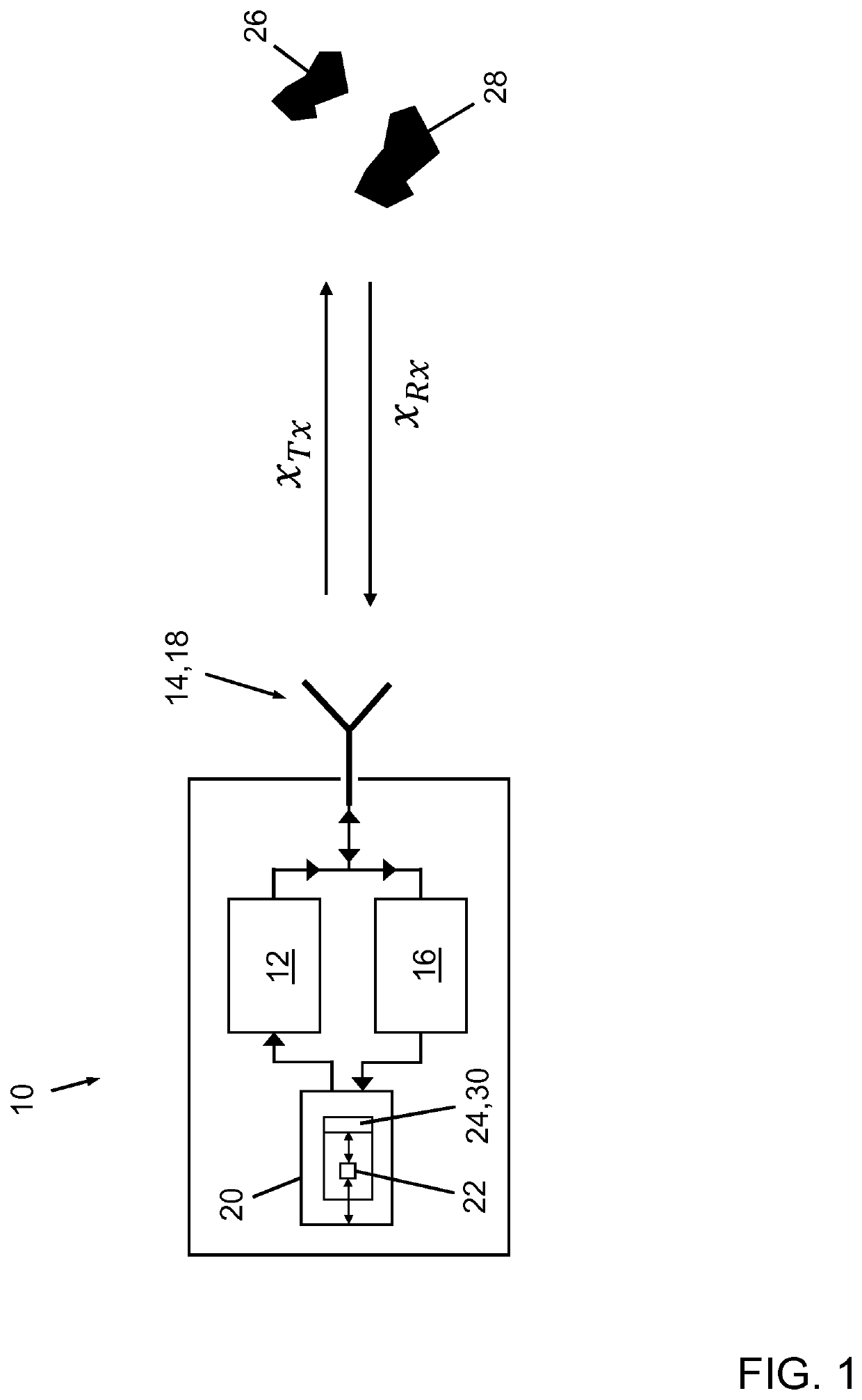
[0052]FIG. 1 schematically illustrates a configuration of an automotive radar system 10 in accordance with an embodiment of the invention and targets 26, 28 of a scene. The automotive radar system 10 is designed as a frequency-modulated continuous wave (FMCW) radar system and is installable in a vehicle such as a passenger car (not shown).

[0053]The automotive radar system 10 comprises a radar transmitter unit 12, a radar receiving unit 16 and an evaluation and control unit 20 that is connected by data links to both the radar transmitter unit 12 and the radar receiving unit 16.

[0054]The radar transmitter unit 12 includes a radar transmit antenna 14 that is directed towards the scene. The radar receiving unit 16 includes a radar receiving antenna 18 that is also directed towards the scene. The radar transmit antenna 14 and the radar receiving antenna 18 are co-located in a monostatic arrangement, which is indicated in FIG. 1 by use of a combined symbol. In this specific embodiment, th...


PUM


Abstract

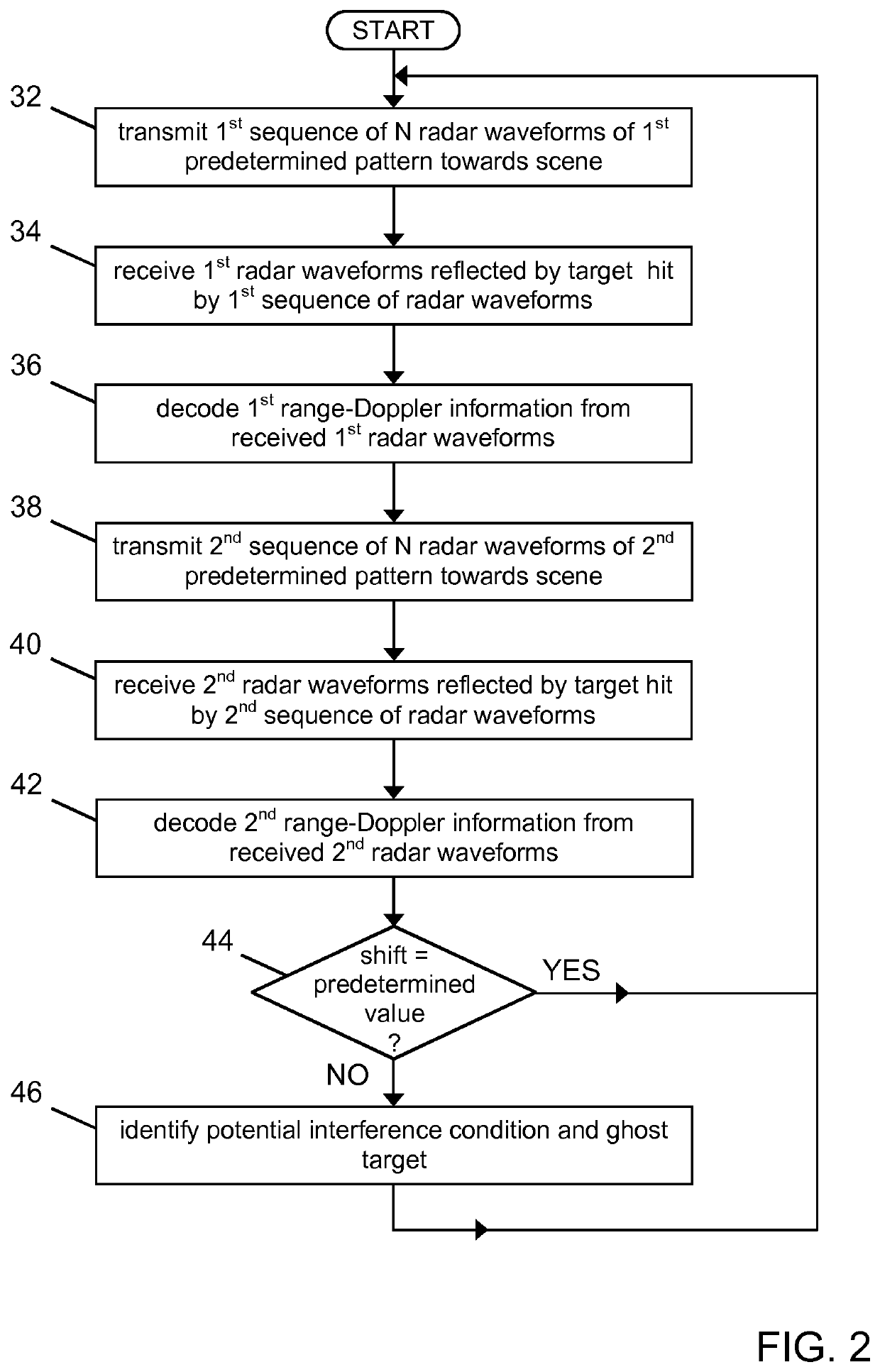
A method of operating an automotive radar system that includes a radar transmitter unit for transmitting radar waveforms towards a scene, a radar receiving unit for receiving radar waveforms that have been reflected by a target in the scene, and an evaluation and control unit for decoding range-Doppler information from the received waveforms. The method includes: transmitting a first sequence of radar waveforms (xTx) and a second sequence of radar waveforms ({tilde over (x)}Tx,k) towards the scene that differs from the first transmitted sequence of radar waveforms (xTx) by predetermined phase shifts (φk) such that each radar waveform ({tilde over (x)}Tx,k) of the second sequence has a different predetermined phase shift (φk). First range-Doppler information and second range-Doppler information are decoded. Deviations of the second range-Doppler information from the first range-Doppler information are compared to at least one predetermined deviation value. Based on the results of the comparing, a potential interference condition is identified.

Description

TECHNICAL FIELD[0001]The present invention generally relates to a method of operating an automotive radar system for avoiding interference by other radar systems, and to an automotive radar system operable pursuant to such method.BACKGROUND OF THE INVENTION[0002]It is known in the art to employ radar technology in exterior automotive applications, such as driver assistance systems, for providing improved safety by facilitating an optimized reaction of a driver of a vehicle with appropriate warnings such as vulnerable road user detection systems, lane change assist systems or blind spot monitoring systems, or even by automatically taking over control of the vehicle, for instance in collision mitigation systems. The most common exterior automotive rated devices operate at radar carrier frequencies in a regime about 24 GHz or about 77 GHz.[0003]With the rapid spread of exterior automotive radar devices, mutual interference of different road users has been recognized as a potential prob...

Claims


Application Information

Patent Timeline
Patent Type & Authority Patents(United States)
IPC IPC(8): G01S7/02G01S7/35G01S13/931
CPCG01S7/023G01S7/354G01S13/931G01S2007/356G01S7/34G01S7/356
Inventor BEISE, HANS-PETERSCHRODER, UDOSTIFTER, THOMAS
Owner IEE INT ELECTRONICS & ENG SA
Learn More