
Optimal feedback heat energy internal combustion engine and applications

a technology of internal combustion engine and heat energy, which is applied in the direction of engine control, climate sustainability, air transportation, etc., can solve the problems of low overall thermo efficiency of conventional internal combustion engine, no transportation device powered by optimal, and extremely low thermo efficiency

Active Publication Date: 2021-01-26
DE ZHEN CORP
View PDF16 Cites 0 Cited by
  • Summary
  • Abstract
  • Description
  • Claims
  • Application Information

AI Technical Summary

Benefits of technology

The OFHE engine achieves significantly higher thermo efficiency and lower weight / power ratio compared to conventional engines, reducing carbon dioxide emissions and enabling more efficient and flexible design of transportation devices.

Problems solved by technology

No related internal combustion engines like the optimal feedback heat energy internal combustion engine.
No transportation device powered by the optimal feedback heat energy internal combustion engine.
The first, under the rational criterion provided by the method developed in this patent, the overall thermo efficiency of conventional internal combustion engines is extremely low.
Obviously, the extremely low thermo efficiency means excessive consumption of fuel and introduces more pollution to the environment.
The other defect of conventional internal combustion engines is that the clumsy moving mechanical mechanisms 801, FIG. 7A or 807, FIG. 7B constitute the majority of the engine assembly construction.
On the contrary the intervening moving mechanical mechanisms consume the developed power output by the media, and restrict the full capacity of power output releasing of the media.
It is the main investment of the industry, and over consumes the natural resources and human resources.
The defects of conventional internal combustion engines were unperceptive at the beginning of applications of the internal combustion engines on transportation devices but seems eminent and unbearable now.
The conventional internal combustion engines have restricted the renovation of transportation devices.
The efforts are deemed powerless due to the defects of conventional internal combustion engines—extremely low thermo efficiency, high weight versus power output ratio, and the parts of power production and power output are bound together by bulk moving mechanical mechanisms.

Method used

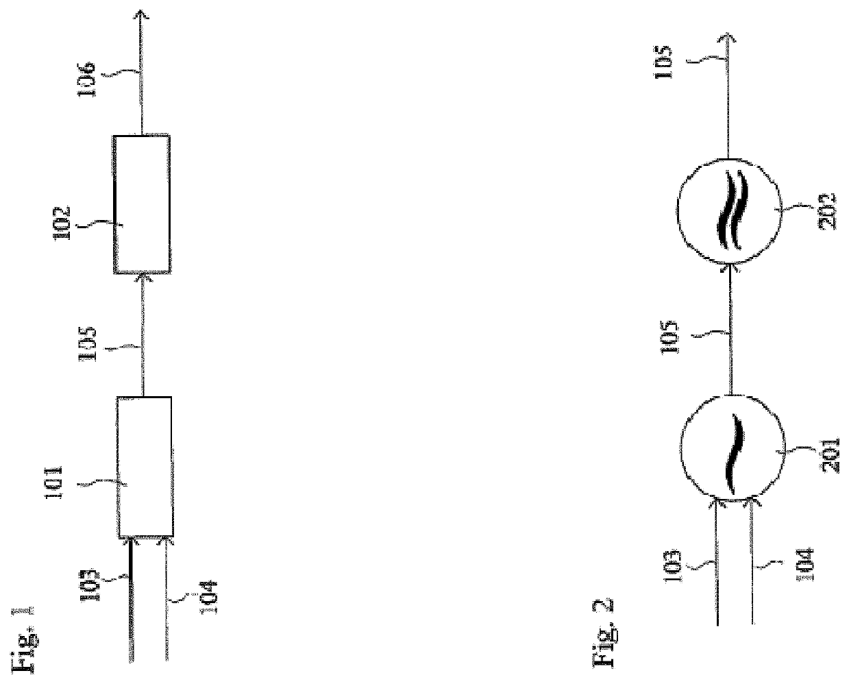
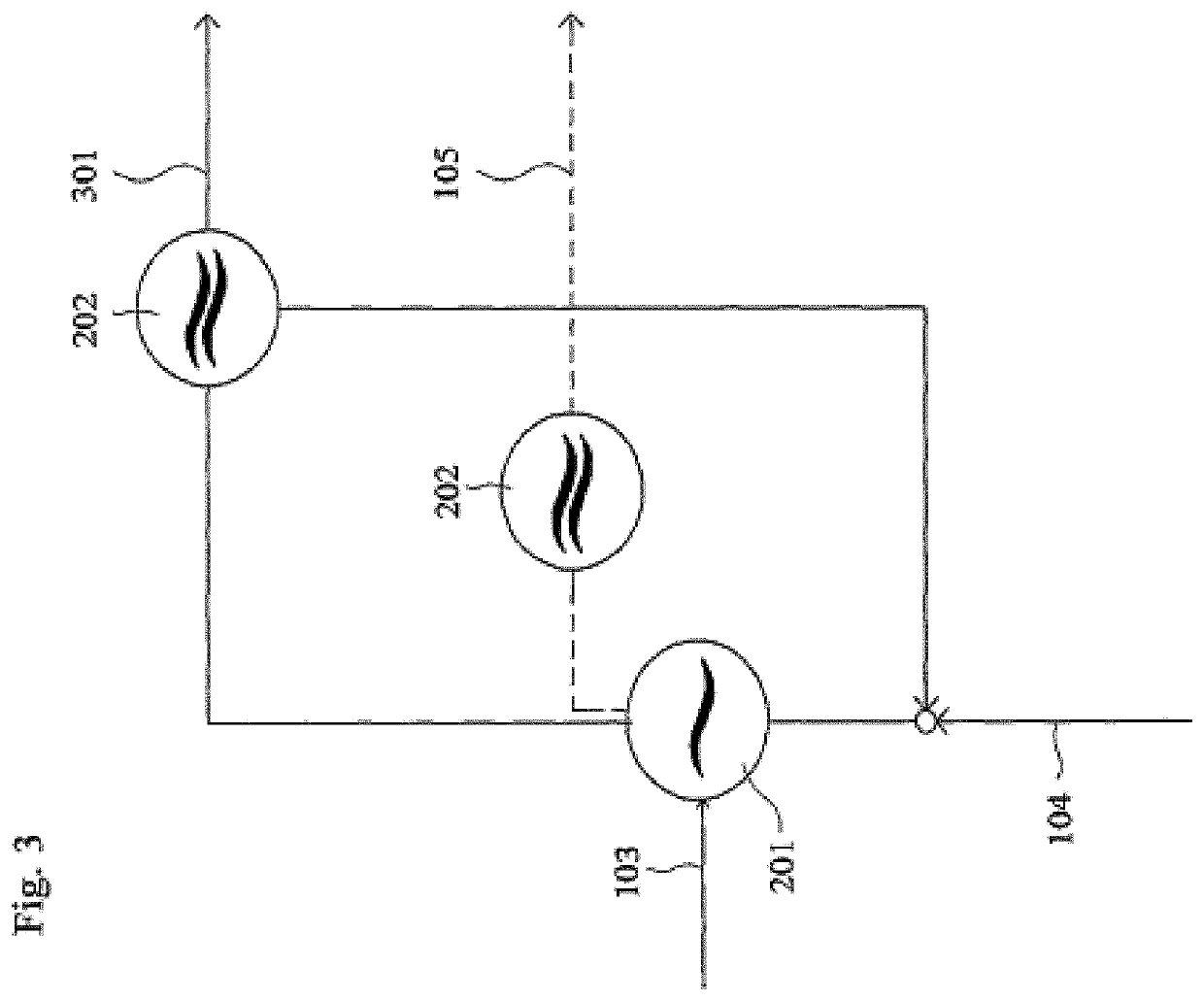
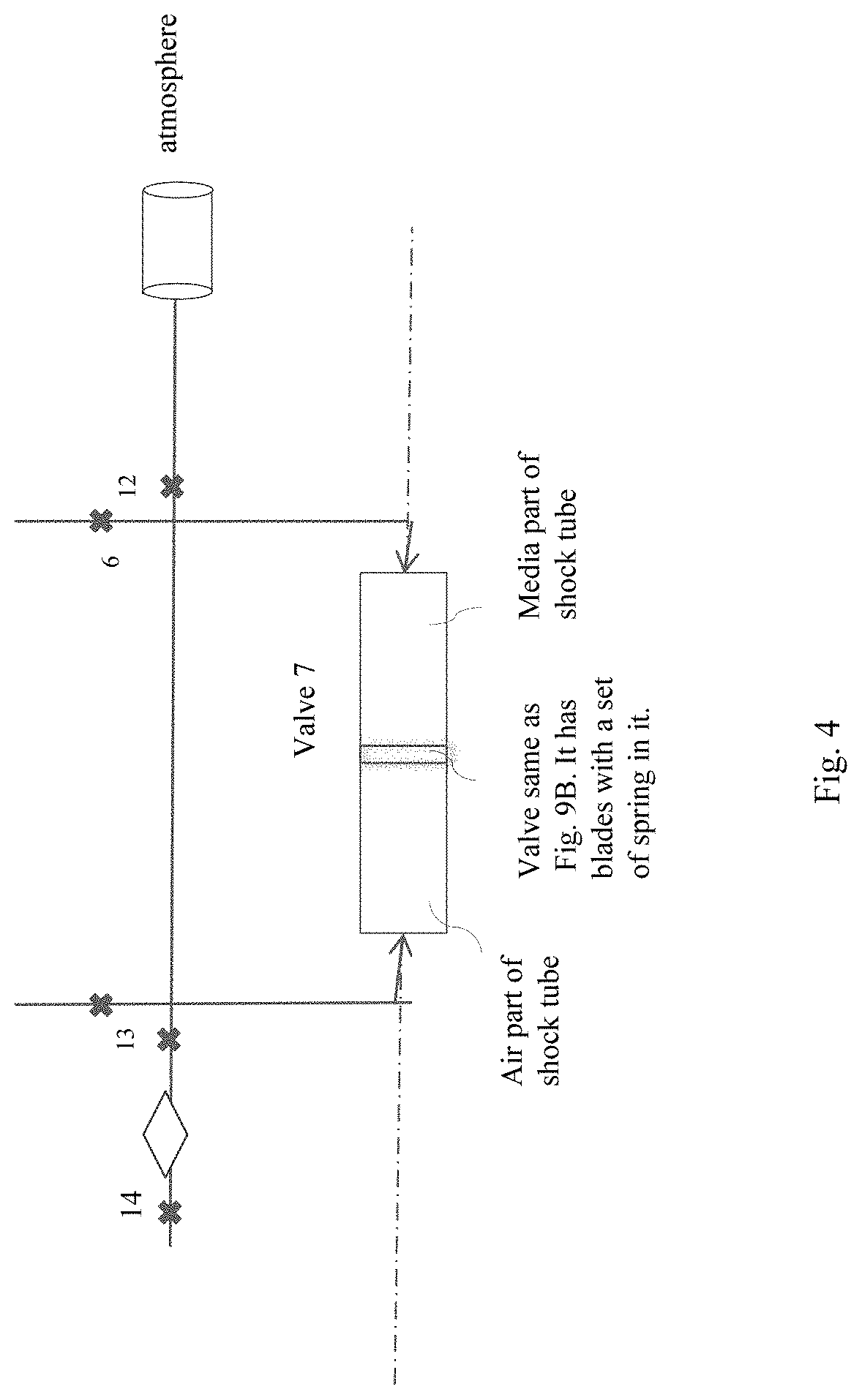

Image

  • Optimal feedback heat energy internal combustion engine and applications
  • Optimal feedback heat energy internal combustion engine and applications
  • Optimal feedback heat energy internal combustion engine and applications

Examples


Embodiment Construction

[0065]The OFHE Internal Combustion Engine and its Applications

[0066]In order to describe the patent in logical scheme of analyses and syntheses, the OFHE internal combustion engine assembly is divided into two groups according to the roles of the parts of engine playing in the working processes of the engine assembly: the active group and passive group. The active group of engine assembly includes parts of engine directly participating the production of the thermo potential heat flow TPHm by combustion of fuel and air and modulated on media. Media are the products of combustion. The passive group of assembly includes parts of engine that consumes TPHm and transforms TPHm into power output of the OFHE internal combustion engine. The analyses of active groups and the passive group, as well as a discussion of the syntheses of the two groups of the OFHE internal combustion engine assembly are discussed below.

[0067]TPH is the shortened form of the term thermo potential heat energy flow o...


PUM


Abstract

An internal combustion engine wherein a thermo potential heat flow in combustion is maximized by providing a feedback of an optimized amount of thermo potential heat flow that is modulated in the exhaust media, into the air intake, and a method of providing feedback comprises producing a shock wave of pulse of exhaust media and pulse of intake air on the opposite side of a high temperature shock tube thereby transferring the thermo potential heat energy flow from the exhaust media to the air intake.

Description

CROSS-REFERENCE TO RELATED APPLICATIONS[0001]This patent application is a continuation-in-part of U.S. application Ser. No. 13 / 498,313, filed Mar. 26, 2012, which is a U.S. National Stage Application filed under § 371 of PCT / AU09 / 01323, filed Oct. 6, 2009, each of which are incorporated herein by reference in their entirety.FIELD[0002]Internal combustion engine.[0003]Field of Applications[0004]Transportation devices, including aircrafts, cars, railway locomotives and trains, marine vessels.[0005]Related Machines and Applications[0006]No related internal combustion engines like the optimal feedback heat energy internal combustion engine. No transportation device powered by the optimal feedback heat energy internal combustion engine.BACKGROUND[0007]The working processes of conventional internal combustion engines were invented a century ago signified by moving mechanical mechanisms intervention the working processes of conventional internal combustion engines. The moving mechanical me...

Claims


Application Information

Patent Timeline
Patent Type & Authority Patents(United States)
IPC IPC(8): F02K7/02
CPCF02K7/02F05D2220/76F05D2220/80F05D2240/35F05D2270/07Y02T50/60
Inventor ZHOU, HAN YUZHOU, HAO
Owner DE ZHEN CORP
Learn More