
Reinforced joint for beam-column connection

a technology of reinforced joints and beam columns, applied in the direction of building types, constructions, building constructions, etc., can solve the problems of steel buildings that are still susceptible to progressive collapse under extreme conditions, steel buildings are often exposed to extreme load events, and the entire building or at least large parts of the building collapse, etc., to improve the resistance of steel-framed buildings

Active Publication Date: 2021-01-26
KING SAUD UNIVERSITY
View PDF16 Cites 7 Cited by
  • Summary
  • Abstract
  • Description
  • Claims
  • Application Information

AI Technical Summary

Benefits of technology

The reinforced joint for a beam-column connection is designed to improve the resistance of steel-framed buildings against progressive collapse caused by damage to columns. This joint can be used as an internal joint in the building frame, and it involves the attachment of stiffening plates to the inner faces of the beams and columns. The stiffening plates provide strength and stability to the joint, making it more resistant to damage. This joint also helps to prevent the beams from bending or buckling under extreme loads, which could cause the building to collapse.

Problems solved by technology

Building frames, such as typical steel building frames, are often exposed to extreme load events, such as those caused by large wind forces, earthquakes, vehicle crashes and blast loads.
However, steel buildings are still susceptible to progressive collapse under extreme conditions due to exposure to blast loads.
Progressive collapse is the propagation of an initial local failure from one part of the building to the adjoining parts, resulting in the eventual collapse of the entire building, or at least large parts thereof.
Unfortunately, effective alternative load paths via catenary action are frequently lacking in present building designs.

Method used


Image

  • Reinforced joint for beam-column connection
  • Reinforced joint for beam-column connection
  • Reinforced joint for beam-column connection

Examples


Embodiment Construction

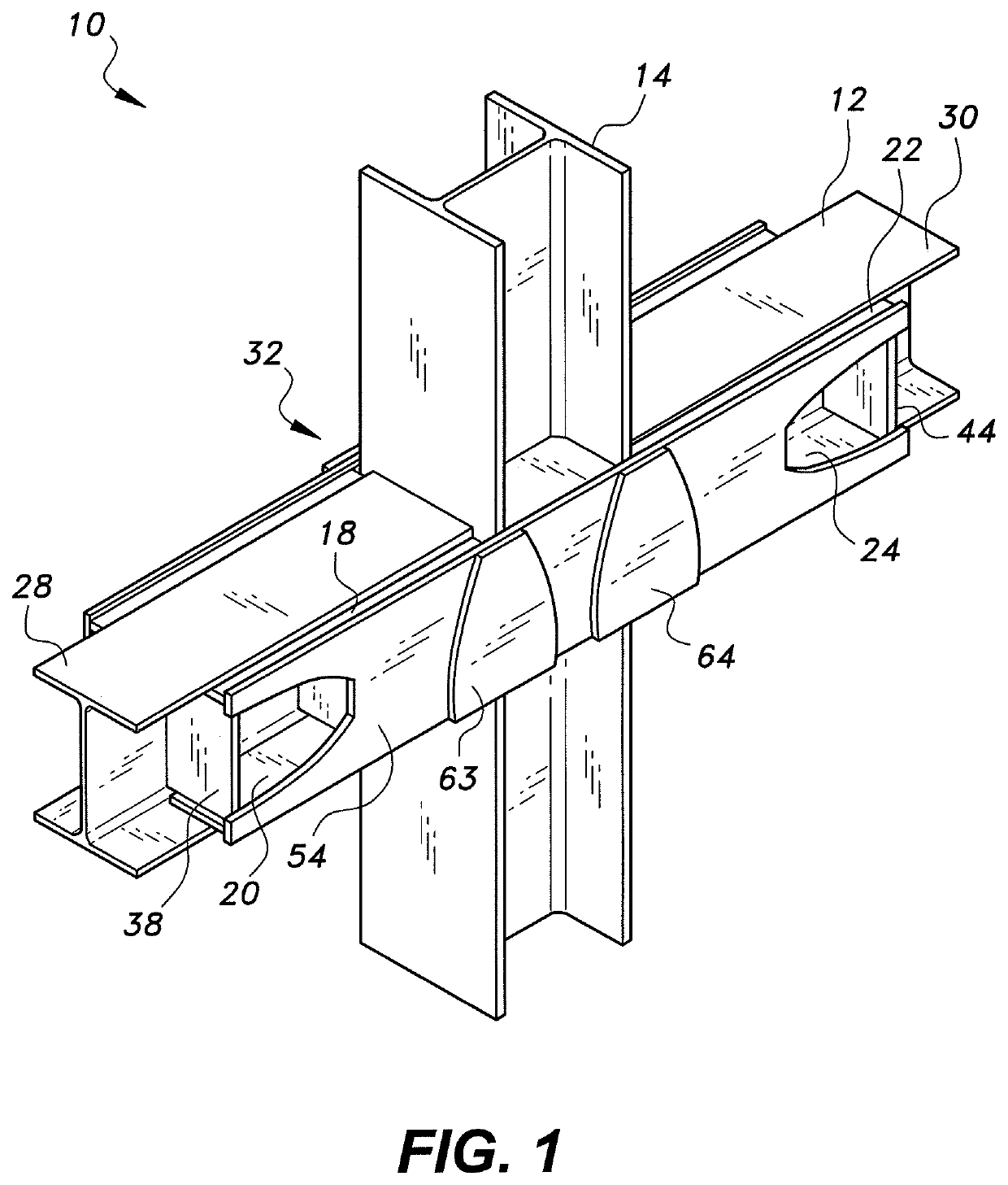
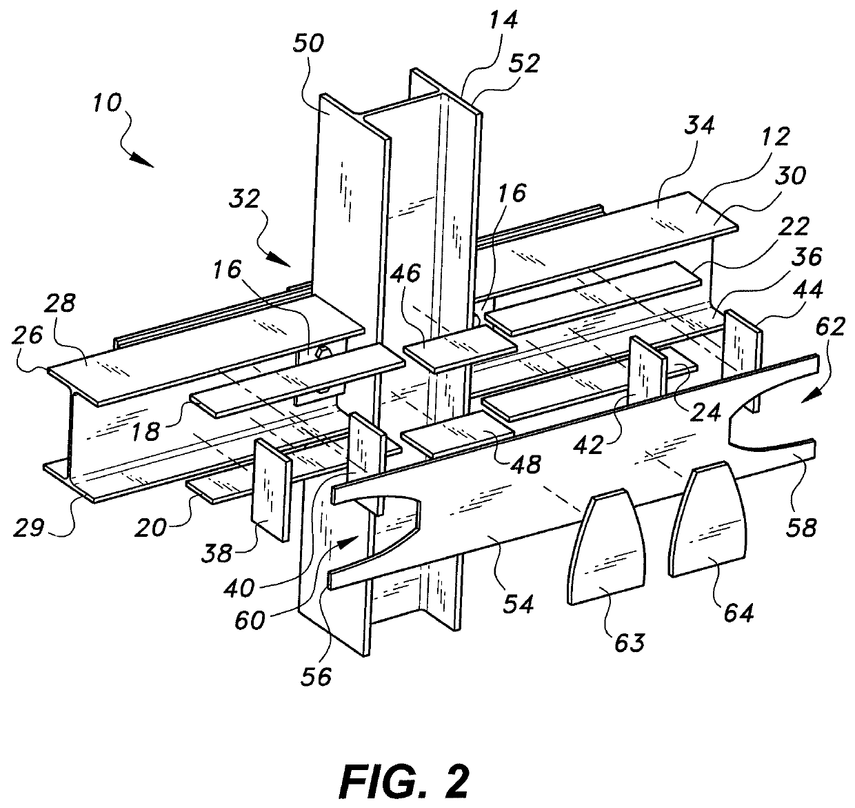
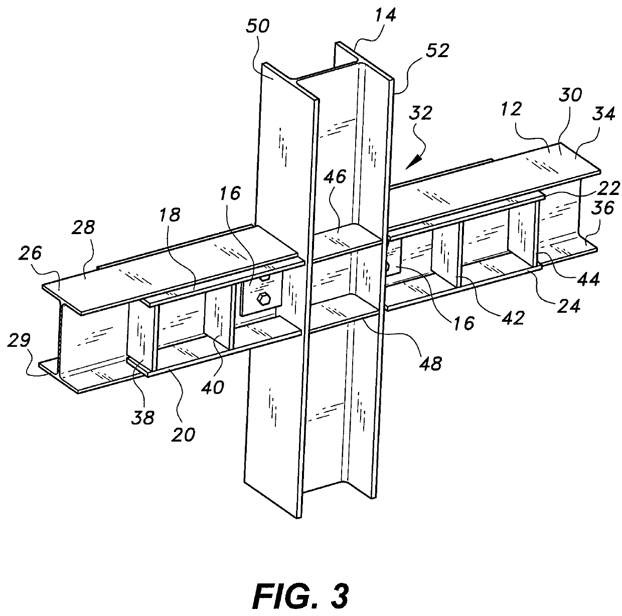
[0025]Referring to FIGS. 1-3, a reinforced joint for beam-column connection 10 is provided for improving the resistance of steel-framed buildings against progressive collapse, such as may be caused by damage to one or more columns as the result of exposure to blast loads or other extreme loads. In FIGS. 1-3, the reinforced joint for a beam-column connection 10 is used as an internal joint in the building frame. As shown, first upper and lower flange stiffening plates 18, 20 are attached to inner faces of upper and lower flanges 26, 29, respectively, of a first structural beam 28 of a set 12 of structural beams. The first upper and lower flange stiffening plates 18, 20 may be welded to the inner faces of the upper and lower flanges 26, 29 of the first structural beam 28. The set 12 of structural beams also includes a second structural beam 30. Second upper and lower flange stiffening plates 22, 24 are attached to inner faces of upper and lower flanges 34, 36, respectively, of the sec...


PUM


Abstract

The reinforced joint for a beam-column connection is provided for improving the resistance of steel-framed buildings against progressive collapse. Flange stiffening plates reinforce flanges of structural beams, with beam web stiffeners being attached to and extending between the flange stiffening plates. Additional column web stiffeners are attached to and extend between flanges of a structural column. A longitudinal cover stiffening plate is attached to the column stiffeners and the flange stiffening plates, extending across the joint and at least partially covering the beam web stiffeners. The reinforced joint between the structural beams and the structural column develops catenary action in the structural beams in the event of collapse.

Description

BACKGROUND1. Field[0001]The disclosure of the present patent application relates to structural joints, and particularly to a reinforced joint for beam-column connection in a steel frame building that uses steel plates welded in the area about the beam-column connection to develop catenary action in the beams in the event of column failure.2. Description of the Related Art[0002]Building frames, such as typical steel building frames, are often exposed to extreme load events, such as those caused by large wind forces, earthquakes, vehicle crashes and blast loads. The ability of steel to yield under external forces is one of the reasons that steel is seen as an ideal building material for structural frames. However, steel buildings are still susceptible to progressive collapse under extreme conditions due to exposure to blast loads. The performance of steel-framed buildings primarily depends on the behavior of the frame's beam-column joints. The properties of the joints are crucial in a...

Claims


Application Information

Patent Timeline
IPC IPC(8): E04B1/24
CPCE04B1/2403E04B2001/2415E04B2001/2445E04B2001/2448E04H9/024E04B2001/2418E04B2001/2484
Inventor ALRUBAIDI, MOHAMMADABBAS, HUSAINELSANADEDY, HUSSEIN M.ALMUSALLAM, TAREK H.AL-SALLOUM, YOUSEF A.
Owner KING SAUD UNIVERSITY
Learn More