
Backlight module and display device

a backlight module and display device technology, applied in the field of display technology, can solve the problems of foreign objects' light leakage and entry, etc., and achieve the effect of increasing the light shielding

Active Publication Date: 2020-12-29
WUHAN CHINA STAR OPTOELECTRONICS TECH CO LTD
View PDF11 Cites 1 Cited by
  • Summary
  • Abstract
  • Description
  • Claims
  • Application Information

AI Technical Summary

Benefits of technology

The invention is a new design for the connection between a frame and a light enhancement sheet in a backlight module and display device. Instead of using a width of connection, liquid glue is used to connect the frame to the light enhancement sheet, preventing the glue from dropping off. This design also includes the addition of a light-shielding effect to further prevent foreign objects such as dust from entering the backlight module and causing product failure. Overall, this invention improves the reliability and durability of the backlight module and display device.

Problems solved by technology

During reliability test, the light-shielding tape easily separates and falls off, resulting in problems such as light leakage and entry of foreign objects.

Method used


Image

  • Backlight module and display device
  • Backlight module and display device

Examples


first embodiment

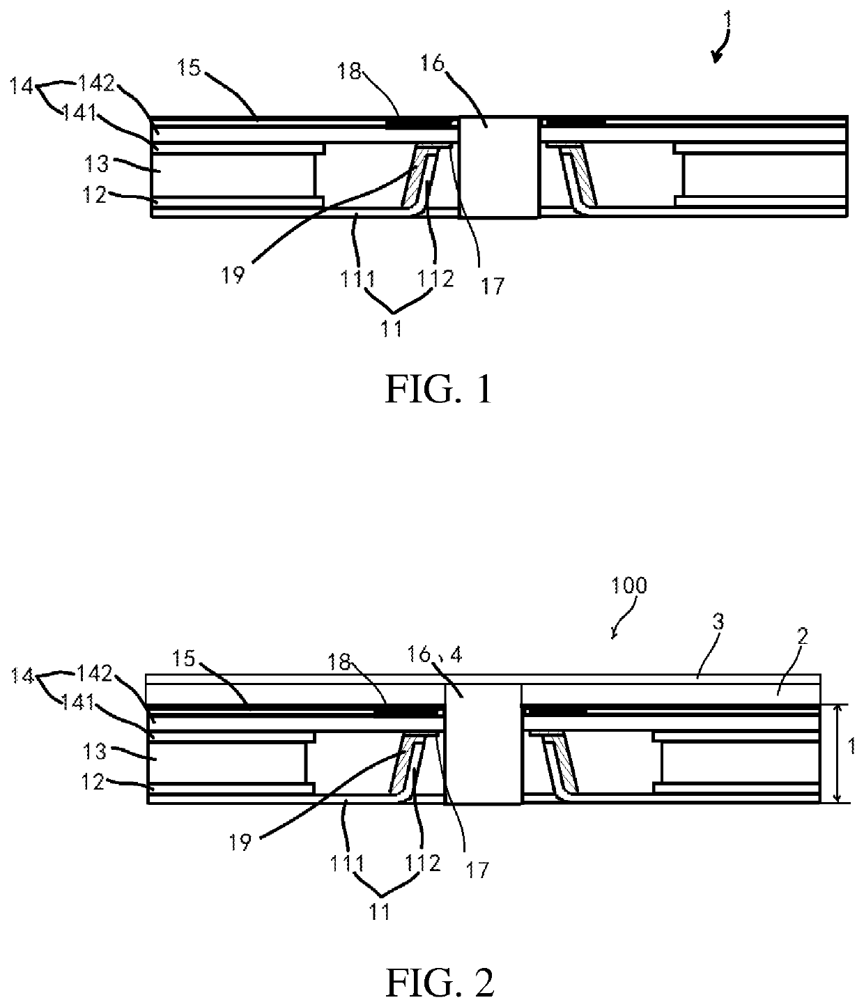
[0027]In a first embodiment, referring to FIG. 1, a backlight module includes a frame body 11, a reflection sheet 12, a light guide plate 13, an optical film group 14, a light-shielding sheet 15, a blind hole 16, and an opaque glue layer 17.

[0028]The frame body 11 includes a frame surface 111 and a connecting part 112 connected to the frame surface 111. In this embodiment, the frame body 11 is an iron frame.

[0029]The reflection sheet 12 is disposed on the frame surface 111. The light guide plate 13 is disposed on the reflection sheet 12.

[0030]The optical film group 14 is disposed on the light guide plate 13. In this embodiment, the optical film group 14 has a light enhancement sheet 142 and a diffusion sheet 141.

[0031]The diffusion sheet 141 is disposed on the light guide plate 13, and the light enhancement sheet 142 is disposed on the diffusion sheet 141. The connecting part 112 is bent from the frame surface 111 to the light enhancement sheet 142, and a top of the connecting part ...

second embodiment

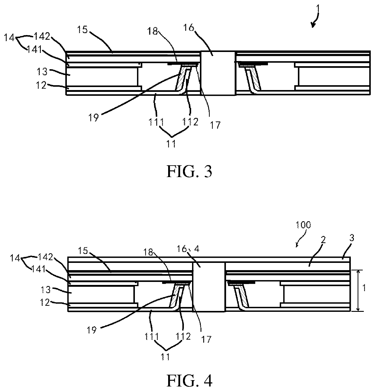
[0037]Referring to FIG. 4, a display device 100 is further provided, and the display device 100 includes the backlight module of the The display device 100 further includes a display screen 2, a cover plate 3, and a camera 4. The light-shielding sheet 15 of the backlight module is disposed on a side of the display screen 2. The cover plate 3 is disposed on a side of the display screen 2 away from the backlight module. The blind hole 16 penetrates from the backlight module to a surface of the cover plate 3. The camera 4 is installed within the blind hole 16.


PUM

PropertyMeasurementUnit
thicknessaaaaaaaaaa
thicknessaaaaaaaaaa
widthaaaaaaaaaa

Abstract

A backlight module and a display device are provided. The backlight module includes a frame body having a frame surface and a connecting part connected to the frame surface; a reflection sheet disposed on the frame surface; a light guide plate disposed on the reflection sheet; an optical film group disposed on the light guide plate, the optical film group includes a light enhancement sheet, and a top of the connecting part is connected to the light enhancement sheet through a plastic frame; a light-shielding sheet disposed on the optical film group; a blind hole, the blind hole penetrates from the frame surface to the light-shielding sheet, and the connecting part is disposed at a periphery of the blind hole; and an opaque glue layer disposed between the plastic frame and the light enhancement sheet.

Description

CROSS-REFERENCE TO RELATED APPLICATIONS[0001]This is the U.S. National Stage of International Patent Application No. PCT / CN2019 / 117000 filed Nov. 11, 2019, which in turn claims the benefit of Chinese Patent Application No. 201910780300.9 filed Aug. 22, 2019.BACKGROUND OF INVENTIONField of Invention[0002]The present invention relates to the field of display technology, and more particularly, to a backlight module and a display device.Description of Prior Art[0003]With development of display technology, display devices, such as mobile phones, are increasingly demanding higher aspect ratio for viewing area; that is, an area ratio of a display area of a display device to a non-display area is increasingly greater. Thus, it is inevitable to adopt irregular display, and some irregular structures are designed as closed shapes (such as circular, rectangular, and other regular or irregular shapes) or open shapes (such as semicircular, rectangular, and other regular or irregular shapes).[0004...

Claims


Application Information

Patent Timeline
Patent Type & Authority Patents(United States)
IPC IPC(8): F21V8/00G02F1/13357G09F9/35H04M1/02
CPCG02F1/133608G02B6/0031G02F1/133606G02B6/0093G02B6/0088G09F9/35H04M1/0264H04M1/0266H04M1/22
Inventor LI, SHENGMING
Owner WUHAN CHINA STAR OPTOELECTRONICS TECH CO LTD
Learn More