
Electrical machine

a technology of electric machines and mechanical disconnects, applied in the direction of interengaging clutches, magnetic circuit rotating parts, magnetic circuit shapes/forms/construction, etc., can solve problems such as safe arrangement, and achieve the effects of improving engagement, increasing friction therebetween, and positive engagemen

Active Publication Date: 2020-12-22
ROLLS ROYCE PLC
View PDF15 Cites 0 Cited by
  • Summary
  • Abstract
  • Description
  • Claims
  • Application Information

AI Technical Summary

Benefits of technology

This patent describes an electrical machine with conical sections that can engage with each other through splines or friction. The machine may have multiple conical sections on the first and second rotor parts, which can be used with different second rotor parts having a single conical section. A bias member is also included to separate the parts from the clutch and ensure they engage fully. The technical effects of this patent are improved engagement between the conical sections and reduced manufacturing costs for different machines.

Problems solved by technology

Advantageously the rotor parts will disengage in the absence of clutch engagement so the arrangement will fail safely if the clutch cannot be energised.

Method used


Image

  • Electrical machine
  • Electrical machine
  • Electrical machine

Examples


Embodiment Construction

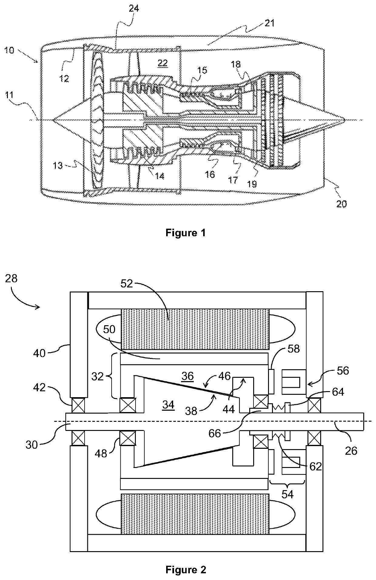
[0029]With reference to FIG. 1, a gas turbine engine is generally indicated at 10, having a principal and rotational axis 11. The engine 10 comprises, in axial flow series, an air intake 12, a propulsive fan 13, an intermediate pressure compressor 14, a high-pressure compressor 15, combustion equipment 16, a high-pressure turbine 17, an intermediate pressure turbine 18, a low-pressure turbine 19 and an exhaust nozzle 20. A nacelle 21 generally surrounds the engine 10 and defines both the intake 12 and the exhaust nozzle 20.

[0030]The gas turbine engine10 works in the conventional manner so that air entering the intake 12 is accelerated by the fan 13 to produce two air flows: a first air flow into the intermediate pressure compressor 14 and a second air flow which passes through a bypass duct 22 to provide propulsive thrust. The intermediate pressure compressor 14 compresses the air flow directed into it before delivering that air to the high pressure compressor 15 where further compr...


PUM


Abstract

An electrical machine comprising a two-part rotor formed of a first rotor part and a second rotor part. The first rotor part includes a conical section and is mounted to a shaft of the machine. The second rotor part has a bore including a complementary conical section. The second rotor part is configured to displace axially between a first state, in which it is engaged with the first rotor part to form the rotor of the electrical machine, and a second state, in which it is axially disengaged from the first rotor part. Also a clutch having an engaged state and a disengaged state. When the clutch is in one of its states the second rotor part is in its first state and switching the clutch to the other of its states axially displaces the second rotor part to its second state.

Description

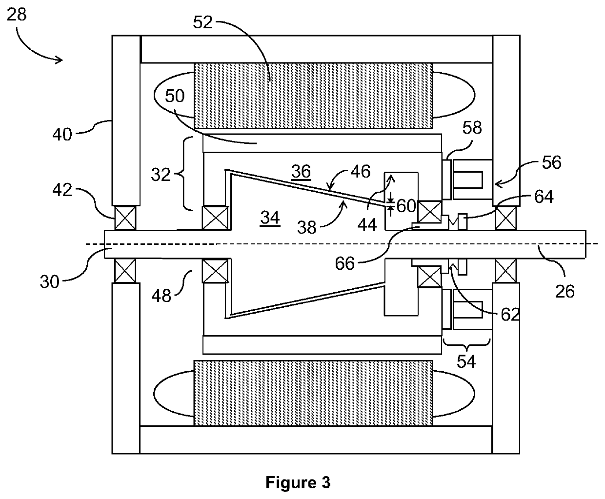
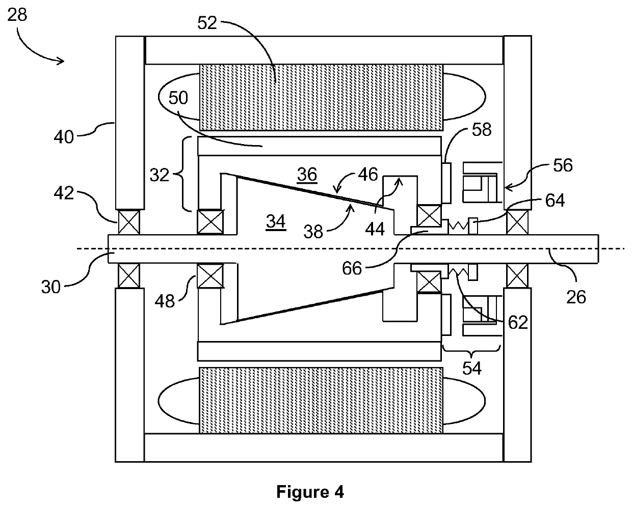
CROSS-REFERENCE TO RELATED APPLICATION[0001]This application is based upon and claims the benefit of priority from British Patent Application Number 1618616.5 filed 4 Nov. 2016, the entire contents of which are incorporated by reference.BACKGROUND[0002]The present disclosure concerns an electrical machine with a mechanical disconnect. In particular it concerns a permanent magnet electrical machine with a mechanical disconnect.BRIEF SUMMARY[0003]According to a first aspect there is provided an electrical machine comprising: a two-part rotor having a rotational axis and formed of: a first rotor part which includes a conical section and which is mounted to a shaft of the machine; a second rotor part which has a bore including a complementary conical section, the second rotor part configured to displace axially between a first state, in which it is engaged with the first rotor part to form the rotor of the electrical machine, and a second state, in which it is axially disengaged from th...

Claims


Application Information

Patent Timeline
Patent Type & Authority Patents(United States)
IPC IPC(8): H02K7/108H02K1/27H02K7/12H02K7/18F16D11/14F16D27/01F16D27/108F16D27/118F02C7/36
CPCF16D11/14F16D27/01H02K7/1823F16D27/108H02K7/1085H02K7/125H02K1/272F16D27/118F05D2260/403F02C7/36Y02E10/72
Inventor JEWELL, GERAINT W.MCLOUGHLIN, ADAM J.CHONG, ELLIS F H
Owner ROLLS ROYCE PLC
Learn More