Power reception device and power transmission device

a power reception device and power transmission technology, applied in the direction of battery data exchange, electrical equipment, exchange data chargers, etc., can solve the problems of increasing the size and thickness of the power reception device, and the reduction of the size and thickness of the device cannot be achieved, so as to reduce the influence of heat generation and the like, the effect of preventing the power from being cut off and not hindering the miniaturization of the power reception devi

Active Publication Date: 2020-12-08
MURATA MFG CO LTD
View PDF21 Cites 0 Cited by
  • Summary
  • Abstract
  • Description
  • Claims
  • Application Information

AI Technical Summary

Benefits of technology

[0005]Accordingly, of the present disclosure provides a power reception device and a power transmission device which prevent power reception of large power and suppress heat generation without hindering miniaturization of the device.
[0007]According to this configuration, when the output voltage increases, by turning on the transistor element, the reception power can be cut off, and the influence of heat generation and the like due to the power reception of large power can be suppressed. This cutoff can be performed only by turning on the transistor element provided in the rectifier circuit. Therefore, it is not necessary to separately provide a circuit for cutting off the reception power, and miniaturization of the power reception device is not hindered.
[0008]The control unit may be configured, in a case where the voltage detected by the voltage detection circuit is higher than the threshold value Va1 and lower than the threshold value Va2, to control operation execution and stoppage of the rectifier circuit, and adjust the reception power by suppressing the output power rather than the rated rectification operation. According to this configuration, when the output voltage is high (equal to or higher than Va2), not by immediately stopping but by executing rectification for suppressing the output power rather than the rated rectification operation, it is possible to suppress transmission efficiency from dropping.
[0011]The parallel capacitor may be configured of a parasitic capacitance component of the transistor element. The transistor element may include a parasitic diode in parallel, and the rectifier circuit may execute a synchronous rectification operation using the transistor element and adjust the reception power. According to this configuration, it is possible to reduce a loss in the rectifier circuit.
[0014]A power transmission device according to the present disclosure includes a power transmission coil configured to couple with a power reception coil included in the power reception device; and an oscillation circuit including a transistor element electrically connected to the power transmission coil and configured to generate a high frequency AC current flowing in the power transmission coil, in which transmission power is adjusted by demodulating a modulation pattern based on a digital signal transmitted from the power reception device. According to this configuration, by adjusting transmission power by the power transmission device, it is possible to suppress the influence of the heat generation and the like due to the power reception of large power in the power reception device.
[0015]According to the present disclosure, when an output voltage increases, by turning on a transistor element, reception power can be cut off, and influence of heat generation and the like due to power reception of large power can be suppressed. This cutoff can be performed only by turning on the transistor element provided in a rectifier circuit. Therefore, it is not necessary to separately provide a circuit for cutting off the reception power, and miniaturization of a power reception device is not hindered.

Problems solved by technology

However, in Japanese Unexamined Patent Application Publication No. 2015-12761, since it is necessary to provide a circuit for controlling the resonant frequency of the resonance circuit, there is a problem in that the power reception device increases in size.
Therefore, when the disclosure of Japanese Unexamined Patent Application Publication No. 2015-12761 is used, there is a risk that reduction in size and thickness of the device cannot be achieved.

Method used


Image

  • Power reception device and power transmission device
  • Power reception device and power transmission device
  • Power reception device and power transmission device

Examples


first embodiment

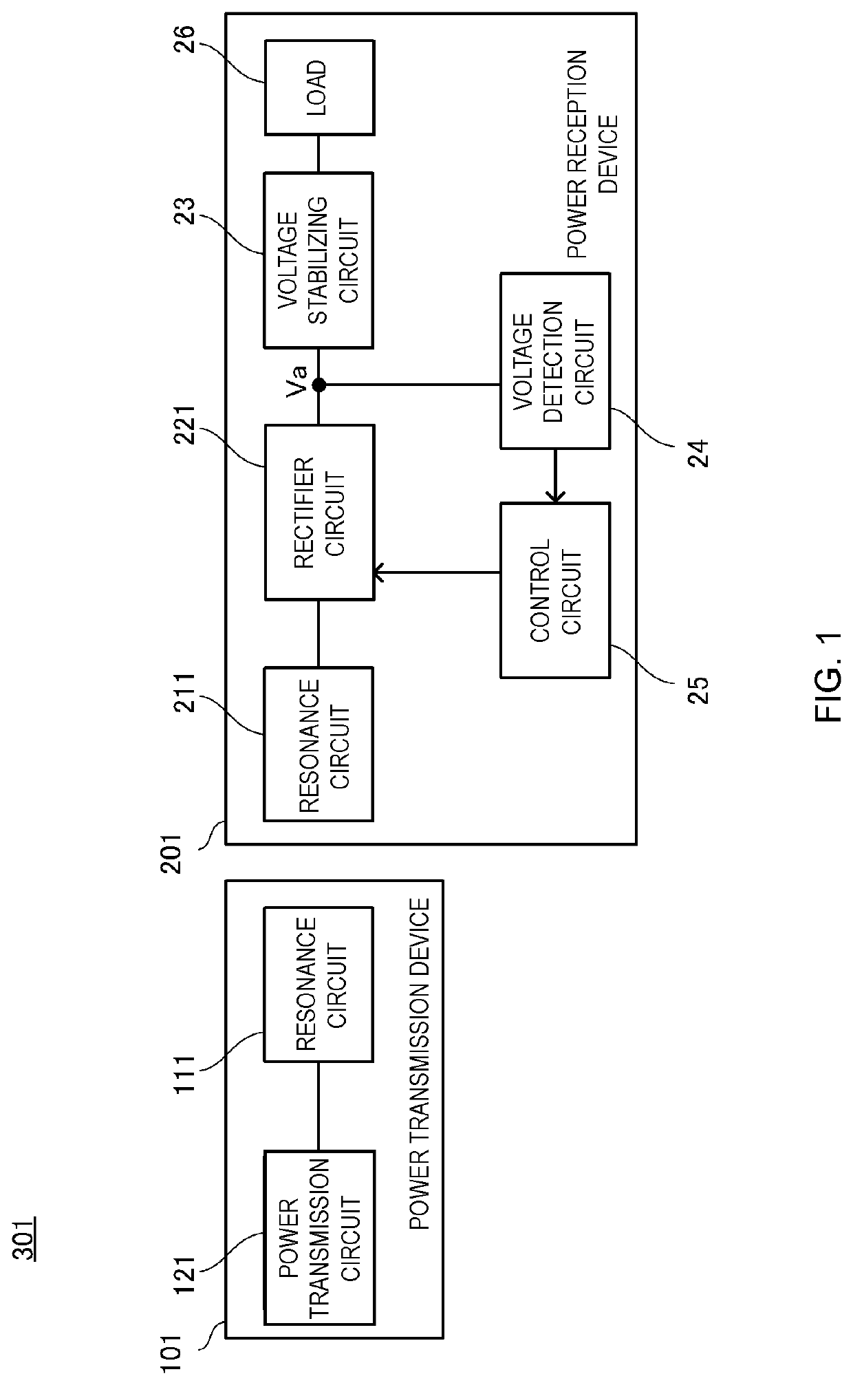
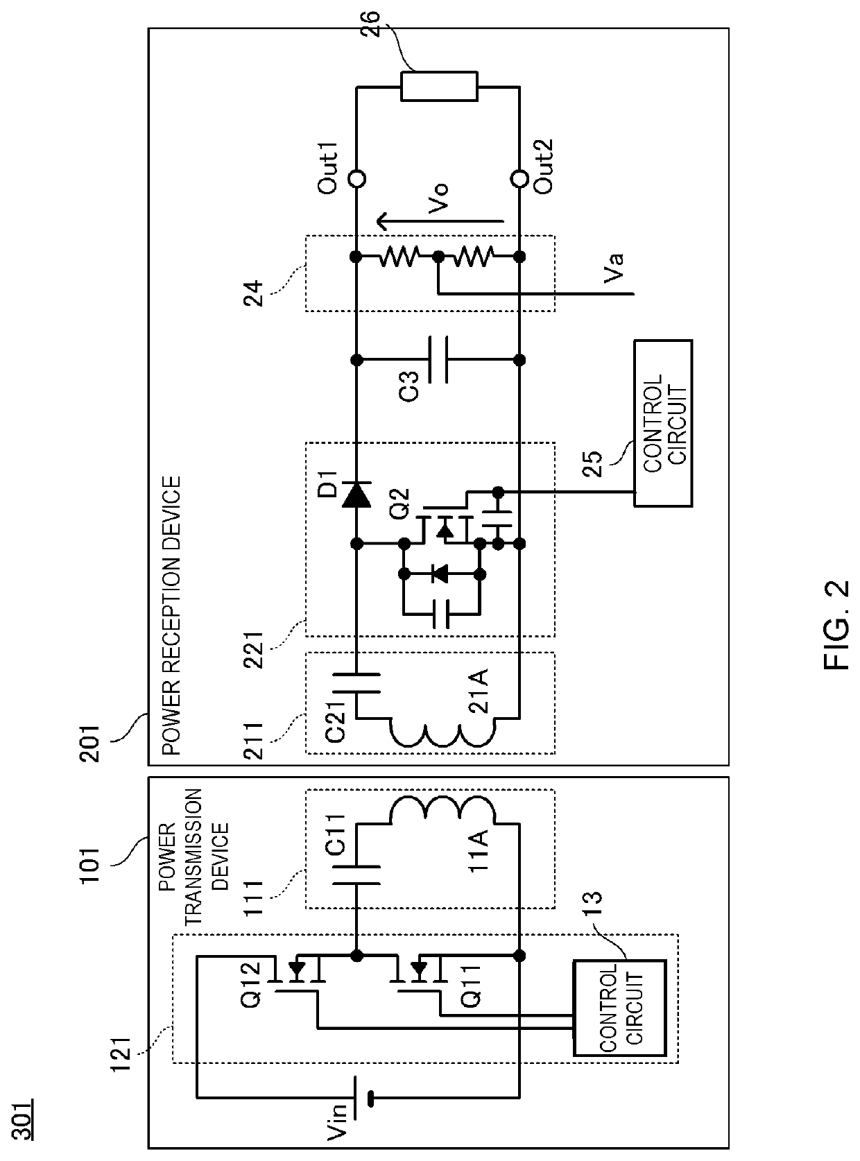
[0033]FIG. 1 is a block diagram of a wireless electric power transmission device, a wireless electric power reception device, and a wireless power supply system configured thereof according to a first embodiment. FIG. 2 is a circuit diagram of the wireless electric power transmission device and the wireless electric power reception device.

[0034]A wireless power supply system 301 is configured of a wireless electric power transmission device (hereinafter, simply referred to as a “power transmission device”) 101 and a wireless electric power reception device (hereinafter, simply referred to as a “power reception device”) 201. The power transmission device 101 is a power supply device which wirelessly supplies power to the power reception device 201. The power reception device 201 is, for example, a portable electronic device such as a smartphone or the like.

[0035]The power transmission device 101 includes a power transmission-side resonance circuit 111 and a power transmission circuit...


PUM


Abstract

A power reception device includes a power reception coil configured to couple with a power transmission coil included in a power transmission device; a rectifier circuit including a diode and a transistor electrically connected to the power reception coil and configured to rectify a high frequency AC current flowing in the power reception coil; outputs configured to output the current rectified by the rectifier circuit to a load; a voltage detection circuit configured to detect an output voltage Va; and a controller configured to control an operation of the transistor based on the output voltage Va. The controller turns off the transistor when the output voltage Va≤the threshold value Va1 is satisfied and causes the rectifier circuit to execute a rated rectification operation, and turns on the transistor when the voltage Va≥the threshold value Va2 is satisfied and stops the rated rectification operation.

Description

CROSS-REFERENCE TO RELATED APPLICATIONS[0001]This application claims benefit of priority to International Patent Application No. PCT / JP2017 / 025704, filed Jul. 14, 2017, and to Japanese Patent Application No. 2016-162411, filed Aug. 23, 2016, the entire contents of each are incorporated herein by reference.BACKGROUNDTechnical Field[0002]The present disclosure relates to a power reception device which is wirelessly supplied with high frequency power from a power transmission device and the power transmission device.Background Art[0003]Japanese Unexamined Patent Application Publication No. 2015-12761 discloses an disclosure in which heat generation of a power reception device in a non-contact power supply system is suppressed. In the non-contact power supply system disclosed in Japanese Unexamined Patent Application Publication No. 2015-12761, power is transmitted from a power transmission device to the power reception device in a non-contact manner by resonance coupling of respective ...

Claims


Application Information

Patent Timeline
Patent Type & Authority Patents(United States)
IPC IPC(8): H02J50/12H02J50/10H02J50/40
CPCH02J50/10H02J50/12H02J50/40H02J50/80H02J7/00034
Inventor HOSOTANI, TATSUYA
Owner MURATA MFG CO LTD
Why Eureka
Try Eureka