Manufacturing method and manufacturing device for peeling member

a manufacturing device and peeling member technology, applied in the field of manufacturing methods and manufacturing devices for peeling members, can solve the problems of paper dirt due to toner, use of automatic sticking machines with an expensive and large structure, and fluororesin film, so as to prevent toner soiling to paper, reduce production costs, and improve the effect of quality

Active Publication Date: 2020-11-24
NTN CORP
View PDF8 Cites 0 Cited by
  • Summary
  • Abstract
  • Description
  • Claims
  • Application Information

AI Technical Summary

Benefits of technology

[0015]The manufacturing method for the peeling member of the present invention includes sticking the non-adhesive resin film. In sticking the non-adhesive resin film, the distal end edge of the distal end portion of the base material is arranged at the side of the adhesive layer of the non-adhesive resin film such that the end portion of the non-adhesive resin film is protruded from the distal end edge, and then the non-adhesive resin film is stuck on both surfaces of the distal end portion of the base material to wrap the distal end edge of the base material by pressing a plurality rollers sequentially onto the non-adhesive resin film from an one side end portion toward an another side end portion in a longitudinal direction of the base material after. Consequently, the non-adhesive resin film can be stuck while suppressing generation of a crinkle or an air bubble in the non-adhesive resin film, and therefore the peeling members with less variation in quality can be obtained. Further, since the tensile force is not applied to the non-adhesive resin film in sticking, the resin film is not contracted in the obtained peeling member, and thereby the peeling member can endure long-time use. Accordingly, toner soiling to a paper can be prevented for a long period of time, and therefore high quality record image can be continuously obtained. Further, even if a projection is formed on the stuck surface, the non-adhesive resin film can be stuck.
[0016]Further, the roller device used in sticking has a simple structure provided with a roller, a linear guide and the like, and therefore a cost of the device can be suppressed. Further, by moving a roller group from one end portion to another end portion, the non-adhesive resin film can be stuck (folded), and thereby the peeling member can be mass-manufactured in a short time.
[0017]In the manufacturing device for the peeling member of the present invention, the film sticking unit includes a plurality of the rollers and the moving unit that moves the rollers relatively to the base material. The rollers are sequentially arranged along the moving direction of the rollers moved by the moving unit, and the rollers includes a plurality of the rollers for folding arranged to be inclined such that angles of surfaces of the rollers against the one surface of the base material are set to gradually larger from the upstream side in the moving direction and a pair of the rollers for finishing arranged to interpose the base material from both surface sides and to follow a plurality of the rollers for folding Further, the manufacturing device for the peeling member is formed use the moving unit to stick the non-adhesive resin film on both surfaces of the distal end portion of the base material to wrap the distal end edge of the base material by pressing the rollers for folding sequentially onto the non-adhesive resin film and interposing the base material from both surface sides by the rollers for finishing. Consequently, the non-adhesive resin film can be stuck while suppressing generation of a crinkle or an air bubble in the non-adhesive resin film, and therefore, similar to the manufacturing method, the peeling members having excellent properties with less variation in quality can be obtained.
[0018]Further, the film sticking unit has a simple structure provided with a plurality of the rollers and the moving unit, and therefore a cost of the device can be suppressed. Further, by moving a roller group from one end portion to another end portion, the non-adhesive resin film can be stuck (folded), and thereby the peeling member can be mass-manufactured in a short time.

Problems solved by technology

However, in the peeling member obtained by this method, since the fluororesin film is stuck while applying the tensile force, in a case in which the adhesive force is deteriorated in long-time use, the fluororesin film is contracted and therefore a paper might get dirt due to the toner stuck to the expose adhesive.
However, according to this method, it is necessary to use an automatic sticking machine having an expensive and large structure.
Further, in a case in which an uneven shape such as a projection is formed on a stuck surface, the sticking of the fluororesin film is impossible, and therefor design of the peeling member is partially restricted.

Method used


Image

  • Manufacturing method and manufacturing device for peeling member
  • Manufacturing method and manufacturing device for peeling member
  • Manufacturing method and manufacturing device for peeling member

Examples


Embodiment Construction

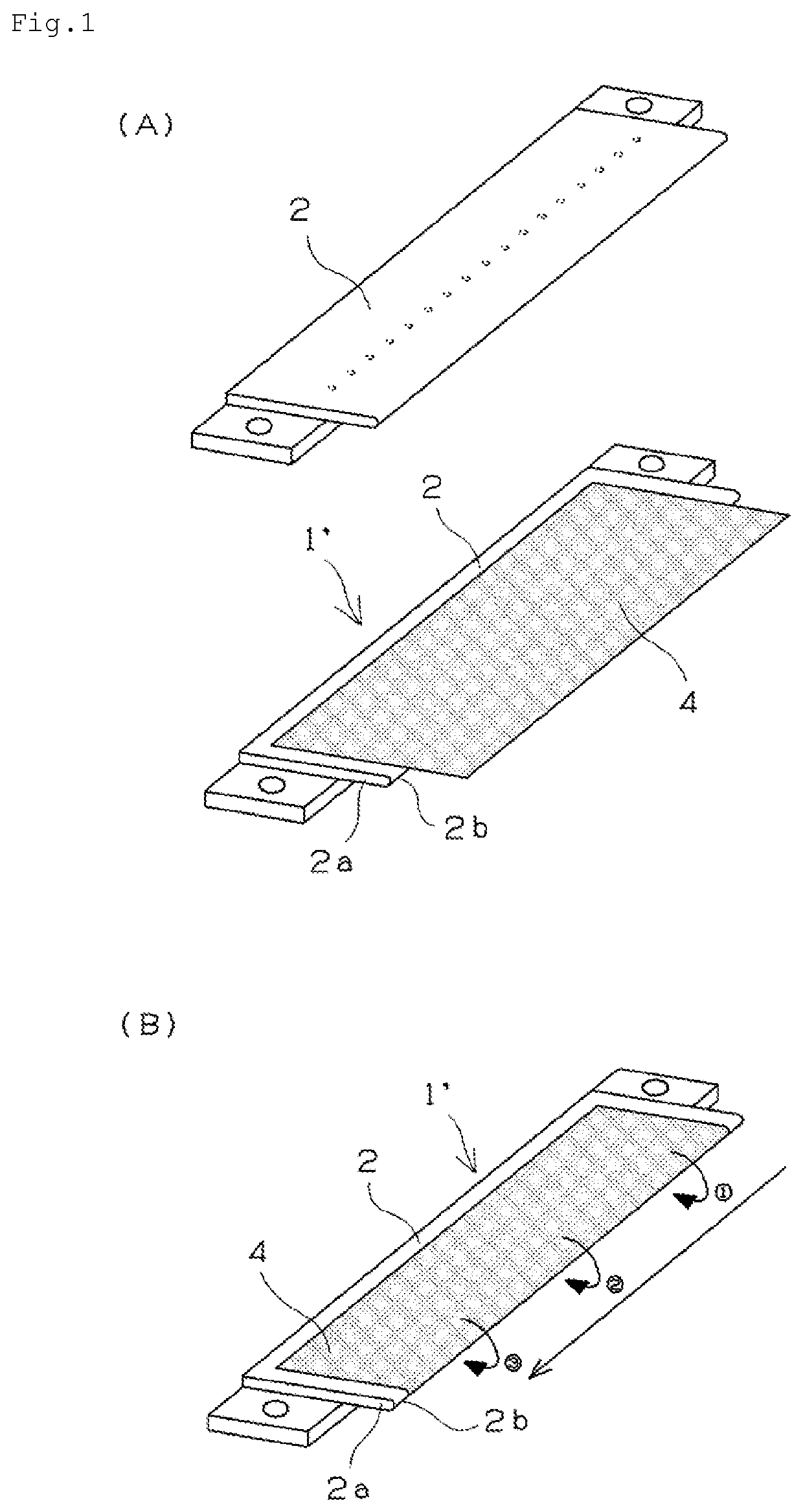
[0028]A manufacturing device for a peeling member of the present invention is formed to manufacture the peeling member provided with a peeling sheet having a base material and a non-adhesive resin film stuck to the base material. In particular, the manufacturing device has a feature in a film sticking unit for sticking the resin film in the peeling sheet. The manufacturing device is used in, for example, a manufacturing method for a peeling member of the present invention described below. FIG. 6 shows the film sticking unit in the manufacturing device. As shown in FIG. 6, a roller device 20 as the film sticking unit is provided for sticking a non-adhesive resin film 4 on both surfaces of a distal end portion 2a of a base material 2, against a base material (composite material 1′) having the non-adhesive resin film 4 stuck to one surface of the base material 2 such that an end portion of the non-adhesive resin film 4 is protruded from a distal end edge 2b of the distal end portion 2a...


PUM

PropertyMeasurementUnit
angleaaaaaaaaaa
angleaaaaaaaaaa
angleaaaaaaaaaa

Abstract

To provide a manufacturing method and a manufacturing device for a peeling member capable of manufacturing the peeling member having less variation in quality and excellent durability for long-time use at a low cost with excellent productivity by a simple structure. The manufacturing method for the peeling member includes sticking a non-adhesive resin film. In sticking the non-adhesive resin film, a distal end edge 2b of a distal end portion 2a of a base material 2 is arranged at a side of an adhesive layer of a non-adhesive resin film 4 such that an end portion of the non-adhesive resin film 4 is protruded from the distal end edge 2b, and then the non-adhesive resin film 4 is stuck on both surfaces of the distal end portion 2a of a base material 2 to wrap the distal end edge 2b of the base material 2 by pressing a plurality rollers 21 to 25 sequentially onto the non-adhesive resin film 4 from an one side end portion toward an another side end portion in a longitudinal direction of the base material 2.

Description

TECHNICAL FIELD[0001]The present invention relates to a manufacturing method and a manufacturing device for a peeling member that peels a paper from a fixing member such as a fixing roller and a fixing belt arranged in an electronic photographic device such as a copying machine and a laser printer.BACKGROUND ART[0002]In an electronic photographic device such as a copying machine and a laser printer, a thermal fixing device that develops an electrostatic latent image, which is formed on a photoreceptor drum, on a paper by using a developing agent such as toner and then fixes the developed image is arranged. The thermal fixing device is provided with a fixing member such as a fixing roller and a fixing belt for fixing the developing agent on a paper by heating and melting and pressing the developing agent.[0003]In the fixing member or a pressing roller that presses the fixing member against a paper, a sheet-like peeling member that peels a paper on which the developing agent is fixed ...

Claims


Application Information

Patent Timeline
Patent Type & Authority Patents(United States)
IPC IPC(8): G03G15/20B29C53/04B65H5/06B65H37/06B29C65/00
CPCB29C66/45B29C53/043B29C66/81467B29C66/81463B65H5/06G03G15/2028B65H37/06Y10T156/1034B29C63/0034B29C63/042B29L2031/767B65H2301/51214
Inventor HIROSE, KAZUOYANAGAWA, HIROSHI
Owner NTN CORP
Why Eureka
Try Eureka