
Method for driving sensorless motor

a sensorless, motor technology, applied in the direction of electrical equipment, electrical commutation motor control, control systems, etc., can solve the problems of large angle estimation errors, torque reduction, step-out, etc., to reduce torque ripples, reduce torque ripples, and improve motor efficiency.

Active Publication Date: 2020-11-17
SHINANO KENSHI
View PDF16 Cites 0 Cited by
  • Summary
  • Abstract
  • Description
  • Claims
  • Application Information

AI Technical Summary

Benefits of technology

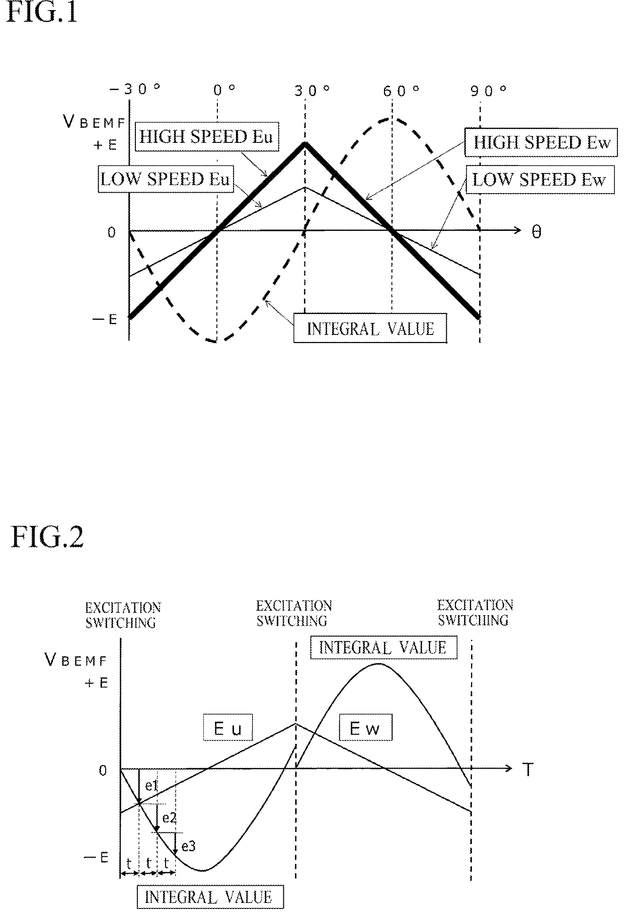
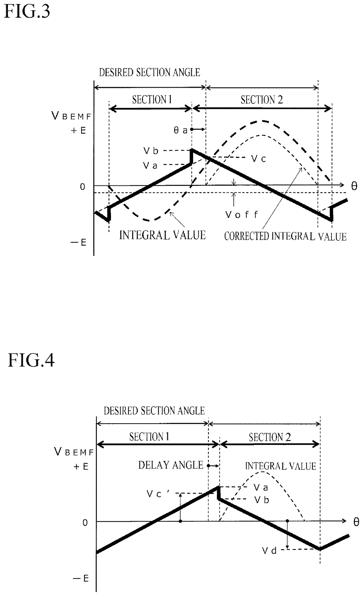
[0043]By employing the above described method for driving the sensorless motor, the excitation switching can be always performed, at an optimum angle in response to a change in speed, by detecting the rotor angle without depending on a time axis, so that a motor efficiency can be highly improved. Further, the output voltage can be increased by reducing torque ripples, a consumption current can be simultaneously reduced, and heat generation of the motor can be reduced. Especially, in a small-sized brushless DC motor having a hall sensor, influences of sensor errors and magnetization errors are large, but the sensorless driving method is not influenced, so an operation efficiency is higher than that of the motor having a hall sensor.
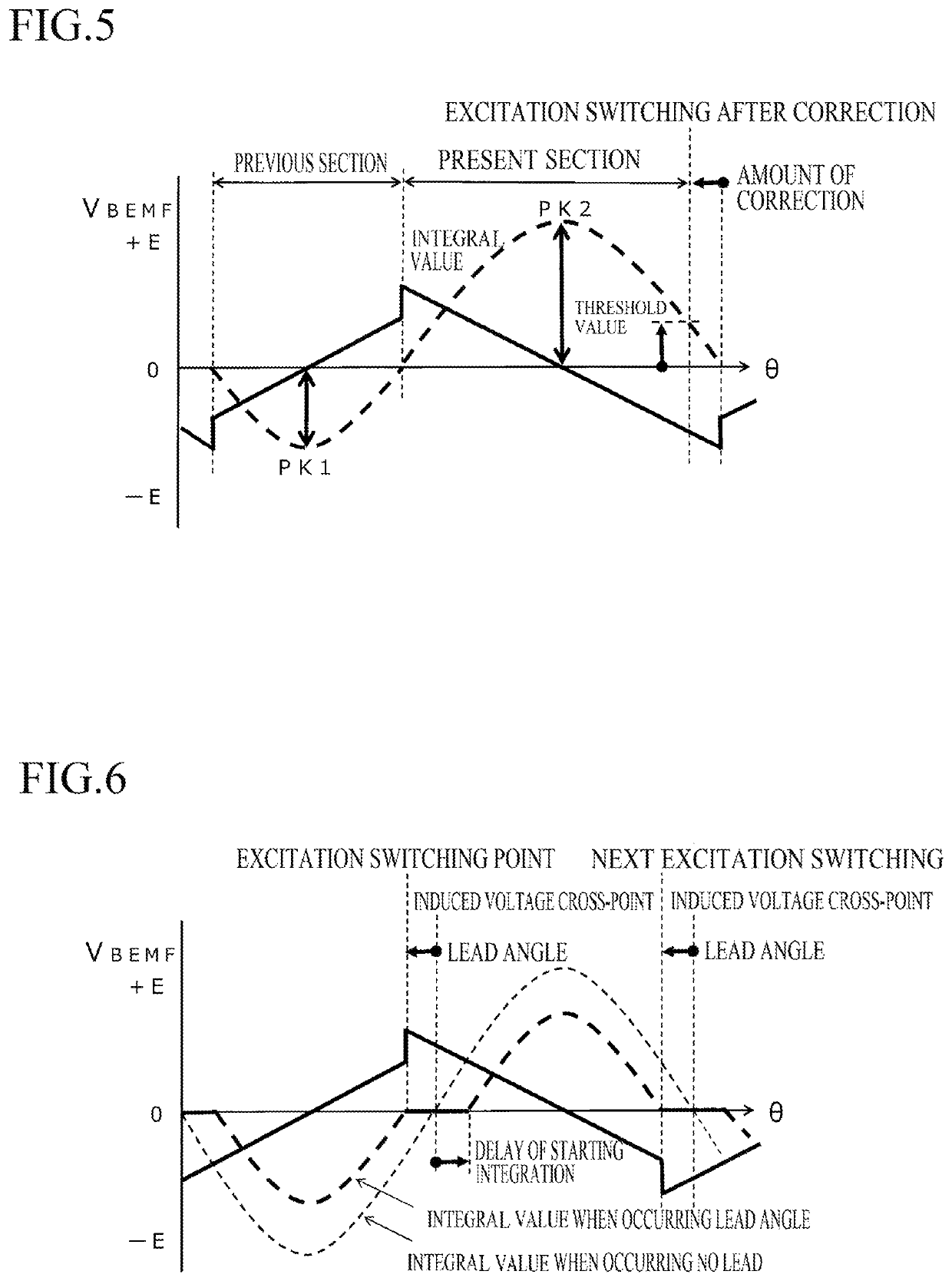
[0044]Further, precise lead angle control can be performed when increasing and reducing speed, spike pulses occurring when the excitation switching is performed are reduced and high frequency waves are restrained, so that rotation noise, which is generated especially in a load operation, can be highly reduced. The lead angle control is capable of effectively generating reluctance torque and is capable of not only improving the motor efficiency but also increasing torque and reducing a consumption current. Further, a field-oriented control, in which the position can be detected while increasing and reducing speed without depending on the speed, is performed, a time of increasing speed can be shortened, the motor can be started in a short time, and deadlock and step-out can be prevented.
[0045]Further, a calculation time for position detection can be short, and a measuring period of induced voltage can be shortened, so a high-speed rotation, whose rotational speed is several times as fast as that of PWM-driven rotation, can be realized in case of performing linear drive.
[0046]Since the method does not depend on motor properties and a load current and is capable of operating without selecting a type of motor and operation conditions, so it can be applied to wide uses. Further, the method can be easily used because setting parameters and adjustment are not required.
[0047]A zero-cross comparator, a hysteresis setting circuit, a common generating circuit, etc. are not required, the circuits can be simpler, an interface part can be constituted by only six dividing resistances, no active parts are required, so that the method can easily applied to a high voltage system, and troubles can be reduced.
[0048]Control programs can be simpler, a developing time of software can be shortened, a high-performance CPU is not required due to small calculation load, and cost for both of hardware and software relating to the driving circuit can be reduced.

Problems solved by technology

In a sensorless vector control system which is a typical sine wave drive system, there are problems that a high-performance A / D converter and a PWM control system which are used for high level control, e.g., FOC (Field Oriented Control) are required and that calculation load of a CPU must be significantly large.
In the conventional sensorless 120°-energization system, the manner for estimating an excitation switching position, which is performed by the timer after detecting the zero-cross point, has a big problem described later.
In case of the small error, only torque and a motor efficiency will be lowered; in case of the large error, a phase is excessively delayed, and deadlock will occur when accelerating speed, and a phase is excessively advanced, torque will be lowered and step-out will occur.
In the conventional manner, position information, i.e., rotor angle, is estimated according to a time axis, so it is impossible to follow speed variation, correct positions can be estimated only when performing at constant speed, and large errors of angle estimation will occur when increasing and reducing speed.
Namely, estimating the rotor angle according to a time axis causes problems, e.g., lowering motor efficiency, reducing torque, vibration, step-out, increasing current, noise generation.

Method used


Image

  • Method for driving sensorless motor
  • Method for driving sensorless motor
  • Method for driving sensorless motor

Examples


Embodiment Construction

lass="d_n">[0064]Embodiments of the method of the present invention for detecting a rotor position of a sensorless motor will now be described with reference to the attached drawings. The present invention can be widely applied to a sensorless driving method for sensorless-driving a sensorless motor comprising: a rotor 2 having a permanent magnetic field 3; and a stator 4 having star-connected coils, which are arranged with a phase difference of 120° and in which phase ends are connected to a motor driving circuit (see FIG. 12).

[0065]A method for sensorless-driving a three-phase DC brushless motor will be explained, as an example, with reference to the structure thereof.

[0066]An example of the three-phase DC brushless motor relating to the present invention is shown in FIG. 12. The three-phase brushless DC motor has a two-pole permanent magnet rotor and a stator 4 having three slots. The motor may be an inner rotor type or an outer rotor type.

[0067]In FIG. 12, the rotor 2 is integra...


PUM


Abstract

The present invention addresses the problem of proposing a method for driving a sensorless motor, wherein the method is different from a conventional rotor position estimation method according to a time axis and performs rotor position estimation according to an angle axis, thus making it possible for excitation switching to always be achieved at an optimal angle in response to a change in speed. According to the present invention, an MCU (5) starts excitation of a coil at an excitation section starting point, measures an induced voltage component generated in the coil by a certain period of energization, integrates the voltage component, and sets an excitation section ending position when the integral value reaches zero. In addition, the motor is continuously rotated by repeating the same integration operation by switching to an excitation pattern in the next excitation section.

Description

TECHNICAL FIELD[0001]The present invention relates to a method for driving a sensor less motor, which is a three-phase sensorless brushless DC motor and driven by rectangular waves and in which a rotor position is detected according to a rotational angle thereof, not a time axis.BACKGROUND ART[0002]Three-phase synchronous motors each of which has a permanent magnetic field and no position sensor are mainly driven by sine waves or rectangular waves. In a sensorless vector control system which is a typical sine wave drive system, there are problems that a high-performance A / D converter and a PWM control system which are used for high level control, e.g., FOC (Field Oriented Control) are required and that calculation load of a CPU must be significantly large. On the other hand, in a sensorless 120°-energization system which is a typical rectangular wave drive system, control can be easily performed, and a cost is low, so this system has been popular and mainly applied to small-size mot...

Claims


Application Information

Patent Timeline
Patent Type & Authority Patents(United States)
IPC IPC(8): H02P6/182
CPCH02P6/182H02P6/157
Inventor YAMAMOTO, KIYOSHI
Owner SHINANO KENSHI
Learn More