
Downhole firing tool

a firing tool and downhole technology, applied in the field of firing switch, can solve the problems of inability to effectively check the wiring of the gun string, inability to diagnose, and inability to continue the firing process, so as to reduce the potential for human error, facilitate handling and installation, and reduce the effect of human error

Active Publication Date: 2020-11-10
GUARDIAN GLOBAL TECH
View PDF38 Cites 21 Cited by
  • Summary
  • Abstract
  • Description
  • Claims
  • Application Information

AI Technical Summary

Benefits of technology

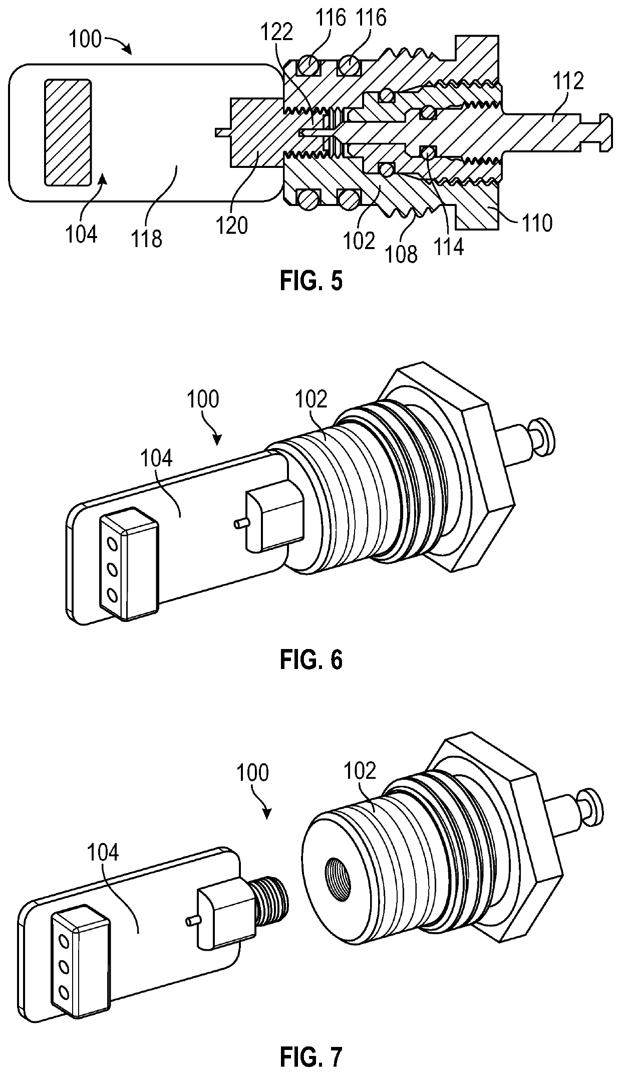
[0025]The provision of the electronic addressable switch mechanically coupled with the body portion allows easy installation of the firing switch in the perforating gun. The electronic addressable switch may be mechanically coupled to the body portion by a removable coupling, for example engagement of corresponding threaded sections, or a bayonet fitting. Alternatively, the electronic addressable switch may be mechanically coupled to the body portion by a permanent coupling, for example soldering, welding, or adhesive. The mechanical coupling of the body portion and electronic addressable switch preferably provides a substantially rigid firing switch, such that the firing switch may be easily handled and installed as a single unit. The electronic addressable switch is dimensioned such that it may be passed through or into the EB switch port of a perforating gun in order to locate the body portion of the firing switch within the EB switch port.
[0026]The electronic addressable switch may comprise a wiring interface. The wiring interface may be arranged to provide an easy and simple connection point for wiring the firing switch. The wiring for the electronic addressable switch is intended to closely mimic that of a conventional EB switch, thus making the steps for connecting it almost identical to that for a conventional EB switch and significantly reducing the potential for human error. The electronic addressable switch wiring may comprise one through wire from the gun above (as per an EB switch), one detonator live wire (as per an EB switch), and one connection to the device below (if required) via the solid pin emanating from the lower end of the addressable switch (as per an EB switch). The wiring may comprise no more than three wires in some embodiments of the invention. The only difference in wiring between an EB switch and the electronic addressable switch is the provision, from the upper end of the electronic addressable switch, of a positively grounded detonator ground wire. The electronic addressable switch may comprise a line in, a detonator firing line, a detonator ground line and a line out. The body portion may comprise a line out. The line in may be connected to the line out of the electronic addressable switch by means of one or more series pass-switches. Alternatively the line in may be connected to the detonator out by means of one or more switches, the detonator line switch(es) and the detonator ground connected to the grounded body portion by means of one or more switches, the detonator ground switch(es). The body portion may comprise an extended pin. The extended pin may comprise the line out. The electronic addressable switch may comprise a male protrusion. The body portion of the firing switch may comprise a female receiving portion. The electronic addressable switch may be connected to the body portion by locating and fixing the male protrusion within the female receiving portion. The fixing may comprise engagement of corresponding threaded sections, or a bayonet fitting, or other conventional fixing techniques as known by the skilled person. It will also be appreciated that the male protrusion may be formed on the body portion and the female receiving portion on the electronic addressable switch. The line in on the electronic addressable switch may connect to the line out of the body portion via the mechanical connection between the electronic addressable switch and the body portion.
[0027]The electronic addressable switch may comprise a microcontroller, for example, a PIC microcontroller. The microcontroller may control aspects of the operation of the electronic addressable switch, including the application of power to a detonator. The control of application of power to a detonator may comprise a Pulse Width Modulation circuit. Those skilled in the art will appreciate that there are many types of logical, electronic controller which may replace the microcontroller described above. The addressable switch may comprise one or more electronically controlled short circuits. The short circuits may comprise one or more switches. The microcontroller may be configured to receive control signals from the line in to the electronic addressable switch. The microcontroller may be programmable to include a unique identifier, for example a unique identifier code. Alternatively, the microcontroller may be programmable to be designated an identifier by an external control device, and store the designated identifier. Such an arrangement allows straightforward configuration of a string of perforating guns including the firing switches, once the string has been assembled.
[0028]The body portion may comprise an external surface with a thread. The threaded part of the external surface may be configured to engage with a correspondingly threaded portion of an EB port. That correspondingly threaded portion of the EB port may, when used with a conventional EB switch, usually be used to retain the EB switch retaining nut. The positive ground may be configured to be wired both to the electronics of the electronic addressable switch and onwards to the ground connection of the detonator. Such an arrangement eliminates the need for a separate grounding point within the gun body or gun sub for the electronic addressable switch or detonator or igniter, that being a common point of failure. The detonator ground wire in a conventional EB switch system may be connected to some, often ill-defined, point of metal within the gun system which might, or might not, offer a low resistance ground path. Therefore, the described arrangement has clear advantages over the conventional grounding techniques.
[0029]The body portion may include a nut. The nut may be arranged to engage the body portion with the EB switch port of the gun sub or perforating gun. The nut, or other external surface on the body portion, may be threaded. The threaded section may be configured to engage with a corresponding threaded section on the gun sub or perforating gun. The body and the nut may be formed of a single piece of material. For example, the body and the nut may be forged or machined out of metal. Providing the body portion with an integrated nut may reduce the time required to install the firing switch. Additionally, the provision of an integrated nut may reduce the number of parts which need to be tracked, stored, and / or provided by a user of the firing switch. The integrated nut may provide the firing switch with a positive ground connection to the perforating gun in which it is installed. The engagement of the body portion with the gun sub or perforating gun may ground the firing switch.
[0031]The firing switch may be configured to be controlled via an addressable voltage switch. The use of an addressable voltage switch may control or otherwise limit the current and / or voltage which is sent to the firing switch. Providing such an arrangement may reduce the rating requirements for components making up the electronic addressable switch. Reducing the rating requirements may enable a smaller electronic addressable firing switch to be provided, thereby making it possible to provide a firing switch as described, particularly with reference to being able to be installed in a conventional EB switch port of a gun sub or perforating gun.

Problems solved by technology

However, in the event of a misfire, it is clear that it will no longer be possible to continue the firing process, because the detonator in the gun above the misfire will not have been made live as described above.
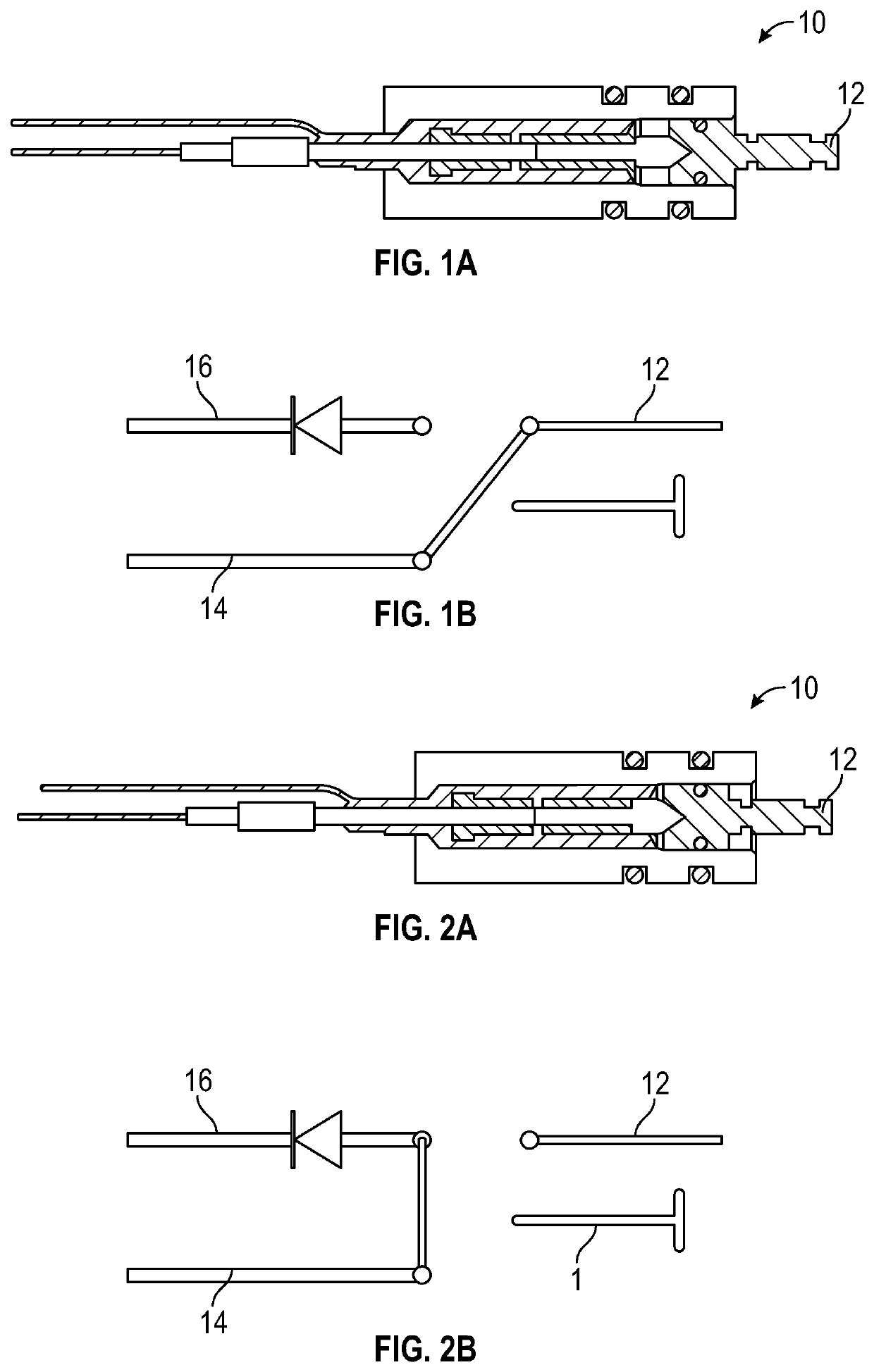
There are a number of additional disadvantages of the mechanical / electrical EB system:1) It is impossible to effectively check the wiring of the gun string before running in hole because only the lowest device(s) is / are connected to the cable which takes power from surface to the gun string.
Some versions of the EB system offer a wire connection to the EB switch retaining nut, but this is relatively fragile and can often break, leading to a misrun.
Electronic addressable switches, whilst being significantly more reliable than EB switches, have a number of disadvantages:
1) Each addressable switch requires a “dummy” EB switch to be installed in the EB port of the perforating gun sub (which connects each gun to the gun above (or below)) in order to provide a pressure isolation barrier between guns.
2) EB switches and dummy EB switches are designed to hold pressure from one direction only, that is from below (guns are always fired lowest first). Bearing in mind the advantage of addressable switches, in that if a gun / switch misfires, the faulty gun can be skipped and the gun above the misfired gun triggered, a situation arises whereby the misfired gun is skipped and therefore contains atmospheric pressure. The gun above the misfired gun is then fired and floods, so it contains high pressure well fluid. The dummy EB switch at the bottom of the fired gun / top of the misfired gun is therefore subjected to pressure from above, a situation for which it is not designed. The dummy EB switch therefore allows well fluid through into the misfired gun, thereby rendering it impossible to diagnose the cause of the misfire.
3) Addressable switches utilise, typically, a slow digital telemetry system for communication between each switch and a surface control panel. This necessitates both good wire connections and a good ground connection for the switch as the ground (body of the gun) is used as the telemetry and power return. In contrast to an EB system, whereby sufficient power can often be sent from surface to overcome corroded or poor ground connections, digital telemetry systems are far more sensitive to such poor connections and an addressable switch system can fail to operate correctly in the presence of poor grounding.
4) Addressable switches such those described are relatively complex and time consuming to install, typically with at least five wires, each of which needs to be connected by a crimp or other connector in order to prepare the switch. These connections are typically: through-wire from above; through-wire to device(s) below; detonator live; detonator ground; and switch ground. It is desirable to reduce the complexity of installation as far as possible, especially considering the field conditions in which the installation may be taking place.
5) Addressable switches are expensive compared to conventional EB switches, and still require the use of a dummy EB switch to operate effectively, further increasing the cost of use.
6) Many addressable switches will include a removable short circuit, arranged to provide RF immunity when the firing switch is on the surface. This short-circuit requires removal before the gun string is run in hole. Failure to remove the short-circuit will mean that the gun misfires. It is possible that users may forget to remove the short circuits on installation, and once the gun string has been constructed, it may be impossible to check whether the short circuit remains in place without activating the switch, which would be extremely dangerous as it could fire the explosive charges on surface.
7) If employing addressable switches, two such devices are required in close proximity to the lower end of the lowest gun, in order to initiate the setting tool and the lowest gun. There is often little space for this in the gun system and suspending the electronic printed circuit board of the addressable switch in open space within the gun system can lead to shorted or damaged connecting wires.

Method used


Image

  • Downhole firing tool
  • Downhole firing tool
  • Downhole firing tool

Examples


first embodiment

[0061]FIG. 5 shows a firing switch 100 according to the invention. The firing switch 100 comprises a body portion 102 mechanically and rigidly coupled to an electronic addressable switch 104. As can be seen, the body portion 102 and electronic addressable switch 104 form a single, substantially rigid, easily installed, part. The body portion 102 comprises an approximately cylindrical outer surface 106, including a threaded section 108. A nut 110 is located towards one end of the body portion 102, away from the end of the body portion 102 mechanically coupled to the electronic addressable switch 104. The nut 110 allows the easy installation of the body portion 102 inside an EB switch port of a gun sub or perforating gun, by engagement of the threaded portion 108 with a corresponding threaded portion of the EB switch port. An end pin 112 extends from the body portion 102, away from the electronic addressable switch 104, such that the distal end of the end pin 112 extends beyond the nu...

second embodiment

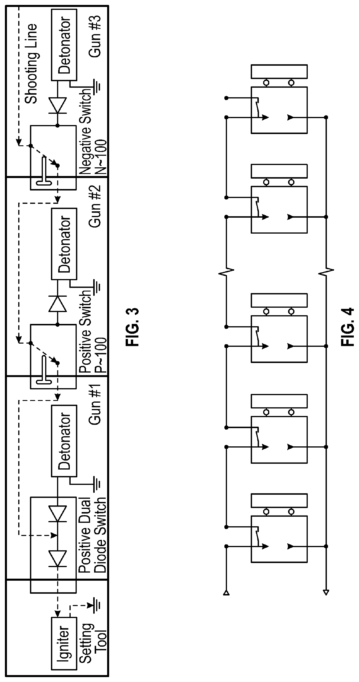
[0071]FIG. 9 is a schematic representation of a string of four perforating guns according to the invention and a setting tool. The setting tool 900 comprises an igniter 904. The igniter 904 is connected to and controlled by an electronic addressable switch 909 of the adjacent perforating gun 906. The igniter 904 is also grounded on the body of the setting tool 900. The bottom perforating gun 900 is connected to the adjacent perforating gun 906. Each of the remaining perforating guns is identical in construction, and so the description of perforating gun 906 can be applied to each of the perforating guns 908, 910, and 912.

[0072]The perforating gun 906 comprises an electronic addressable switch 909 mechanically and rigidly connected to a body portion 911. The electronic addressable switch 909 includes an interface with a line in 913, a detonator line out 914, and a detonator ground line 916. The detonator line out 914 runs to a detonator 918. The perforating gun 906 also comprises a l...


PUM


Abstract

The invention relates to downhole firing tools. In particular, a firing switch for a perforating gun with an EB switch port. The firing switch comprises a body portion configured to be located within the EB switch port, and an electronic addressable switch mechanically coupled to the body portion. The mechanical coupling of the body portion and electronic addressable switch may provide a substantially rigid firing switch.

Description

FIELD OF THE INVENTION[0001]The present invention concerns a firing switch. More particularly, but not exclusively, this invention concerns a firing switch for a perforating gun.BACKGROUND OF THE INVENTION[0002]The oil and gas industry uses perforating guns (explosive devices) to create holes in steel well casings to enable hydrocarbons to flow from a reservoir into a wellbore. Often strings coupling a plurality of perforating guns are sent downhole, in order to enable a number of clusters of holes to be created in a single downhole operation. Selective perforating is a technique widely used to individually fire perforating guns in such strings, when each gun is at the required well depth. For example, a string of five guns may be sent downhole, to a depth at which the lowest gun in the string is to be fired. The lowest gun is then fired, and the string moved to a position where the second lowest gun is at the required depth. The second lowest gun is fired, and the process repeated ...

Claims


Application Information

Patent Timeline
Patent Type & Authority Patents(United States)
IPC IPC(8): F42D1/04E21B43/1185
CPCE21B43/1185F42D1/043E21B43/11E21B43/116
Inventor MAXTED, IAINCURNOCK, PAUL
Owner GUARDIAN GLOBAL TECH
Learn More