
Multi-function speaker

a multi-functional speaker and speaker technology, applied in the field of electroacoustic conversion, can solve problems such as limiting the performance of multi-functional speakers

Active Publication Date: 2020-11-03
AAC TECH PTE LTD
View PDF4 Cites 0 Cited by
  • Summary
  • Abstract
  • Description
  • Claims
  • Application Information

AI Technical Summary

Benefits of technology

This configuration reduces the resonant frequency (f0) and improves the low-frequency vibration performance of the speaker, enhancing its overall operational efficiency.

Problems solved by technology

Therefore, the structure of the speaker in the related art results a larger f0 of the multi-function speaker when the speaker operates at low frequencies, thereby limiting the performance of the multi-function speaker.

Method used


Image

  • Multi-function speaker
  • Multi-function speaker
  • Multi-function speaker

Examples


Embodiment Construction

[0014]The present disclosure is described in detail hereinafter with reference to an exemplary embodiment. For clearer descriptions, technical solution and beneficial effects of the present disclosure, the present disclosure is described in further detail together with the figure and the embodiments. It should be understood the specific embodiments described hereby is only to explain the disclosure, not intended to limit the disclosure.

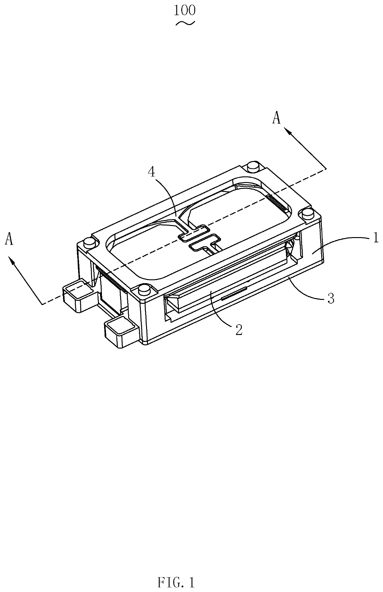
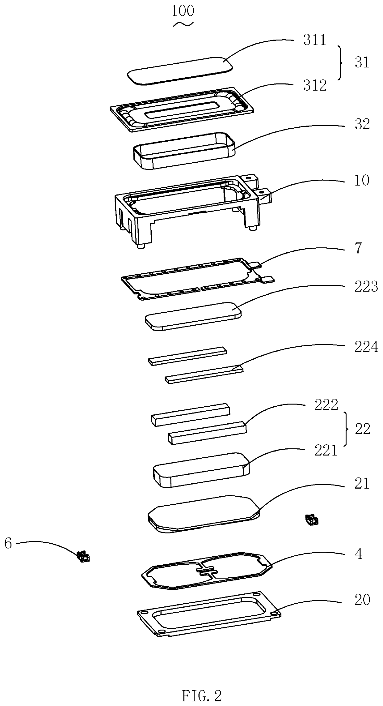
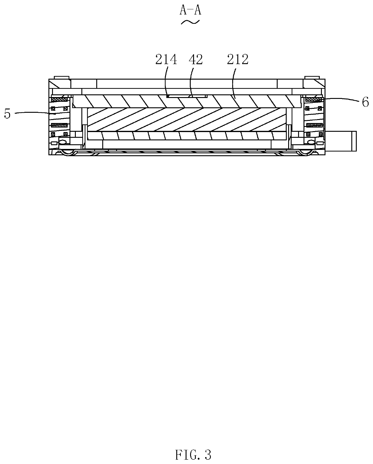
[0015]Referring to FIG. 1 and FIG. 2, FIG. 1 is an isometric view of a multi-function speaker according to the present disclosure, and FIG. 2 is an exploded view of the multi-function speaker according to the present disclosure. The present disclosure provides a multi-function speaker 100. The multi-function speaker 100 includes a frame 1 having a receiving space, a magnetic circuit system 2, a vibration system 3 and an elastic member 4. The magnetic circuit system 2 and the vibration system 3 are received in the receiving space of the frame 1. The el...


PUM


Abstract

A multi-function speaker includes a frame having a receiving space, a magnetic circuit system, a vibration system, and an elastic member configured to suspend the magnetic circuit system in the receiving space. The frame includes two first side portions oppositely arranged, and two oppositely disposed second side portions connecting the two first side portions. The magnetic circuit system includes a lower plate, and a magnet assembly disposed on the lower plate.

Description

FIELD OF THE DISCLOSURE[0001]The present disclosure relates to electro-acoustic conversions, and more particularly to a multi-function speaker applied in a portable electronic product.DESCRIPTION OF RELATED ART[0002]With the rapid social development, popularity of audio devices is getting higher and higher. Among masses of recreational and entertainment methods, high-quality music is gradually popularized. Therefore, speakers for playing audios are widely used in today's smart mobile devices.[0003]A speaker in the related art includes a frame having receiving space, a vibration system, a magnetic circuit system and an elastic member. The magnetic circuit system is suspended in the receiving space of the frame by the elastic member.[0004]The magnetic circuit system includes a yoke, a primary magnet and a secondary magnet received in the yoke. The primary magnet and the secondary magnet form a magnet assembly accommodated in the yoke, and a magnetic gap is formed between the magnetic ...

Claims


Application Information

Patent Timeline
Patent Type & Authority Patents(United States)
IPC IPC(8): H04R9/06H04R9/02H04R1/02
CPCH04R1/02H04R9/06H04R9/025H04R2400/11H04R2499/11H04R2400/03
Inventor ZHOU, JIASHENGZHANG, LONG
Owner AAC TECH PTE LTD
Learn More