Coaxial cable

a coaxial cable and cable technology, applied in coaxial cables/analogue cables, cables, electrical equipment, etc., can solve the problems of large friction between the strands constituting the outer conductor, insufficient flexibility, poor productivity, etc., and achieve excellent shielding characteristics and small friction

Active Publication Date: 2020-11-03
JUNKOSHA
View PDF8 Cites 0 Cited by
  • Summary
  • Abstract
  • Description
  • Claims
  • Application Information

AI Technical Summary

Benefits of technology

[0009]The present invention has been made in view of the above-mentioned problems, and an object thereof is to provide a thin coaxial cable which has a small outer diameter, is flexible, can be used in a minute space, and has excellent shielding characteristics.
[0011]In the coaxial cable according to the present invention, since the outer conductor is formed by laterally winding strands having outer diameters different from each other by 10% or more by mixing them in the same direction, the strands can be compressed without applying excessive load, gaps are not generated between the strands, leakage of electromagnetic waves and intrusion are suppressed, and excellent shielding characteristics can be obtained. The coaxial cable according to the present invention is superior in shielding characteristics to a conventional coaxial cable having a braided structure of an outer conductor and a double lateral winding structure, and can have an outer diameter smaller than that of a conventional coaxial cable having a braided structure of an outer conductor and a double lateral winding structure.
[0013]Since the ratio of the outer diameter of the large-diameter strand to the outer diameter of the small-diameter strand in the strands constituting the outer conductor of the coaxial cable according to the present invention is (outer diameter of the large-diameter strand) / (outer diameter of the small-diameter strand)=1.25 to 5.00, it is possible to particularly efficiently compress the strands, and the shielding characteristic is improved. Furthermore, even when the cable is bent, a gap is not generated between the strands, and the load caused by the rubbing of the strands is reduced.
[0015]Since the outer conductor of the coaxial cable according to the present invention is formed by mixing strands having diameters different from each other by 10% or more, it is possible to set the lateral winding density to 1.0 or more by suppressing the influence on the outer diameter and the appearance of the coaxial cable. By setting the lateral winding density to 1.0 or more, a gap is not generated between the strands, and the strands of the outer conductor are compressed to obtain excellent shielding characteristics.

Problems solved by technology

(Patent Document 1) Although the coaxial cable having the outer conductor of the braided structure is excellent in the shielding characteristics, there is a problem that the outer diameter becomes large, friction between the strands constituting the outer conductor is large, flexibility is not sufficient, and productivity is poor.
On the other hand, a coaxial cable provided with a lateral winding as an outer conductor of the coaxial cable is excellent in flexibility, but is not sufficient in terms of shielding characteristics for shielding noise.
This has a problem in that the winding directions of the lateral windings of the respective layers are different from each other, and the friction between the strands constituting the outer conductor is large like the braided structure, and the flexibility is not sufficient.
In addition, since the lateral winding is doubled, the outer diameter is increased correspondingly, and the productivity is also inferior.

Method used


Image

  • Coaxial cable
  • Coaxial cable
  • Coaxial cable

Examples


embodiment

[0052]A coaxial cable was prepared so that the characteristic impedances were substantially equal, and the far-end crosstalk was measured by changing the frequency of the transmission signal as a two-core parallel cable in which two cores were arranged in parallel. By suppressing the crosstalk, the shielding characteristic of the coaxial cable can be confirmed.

example 1

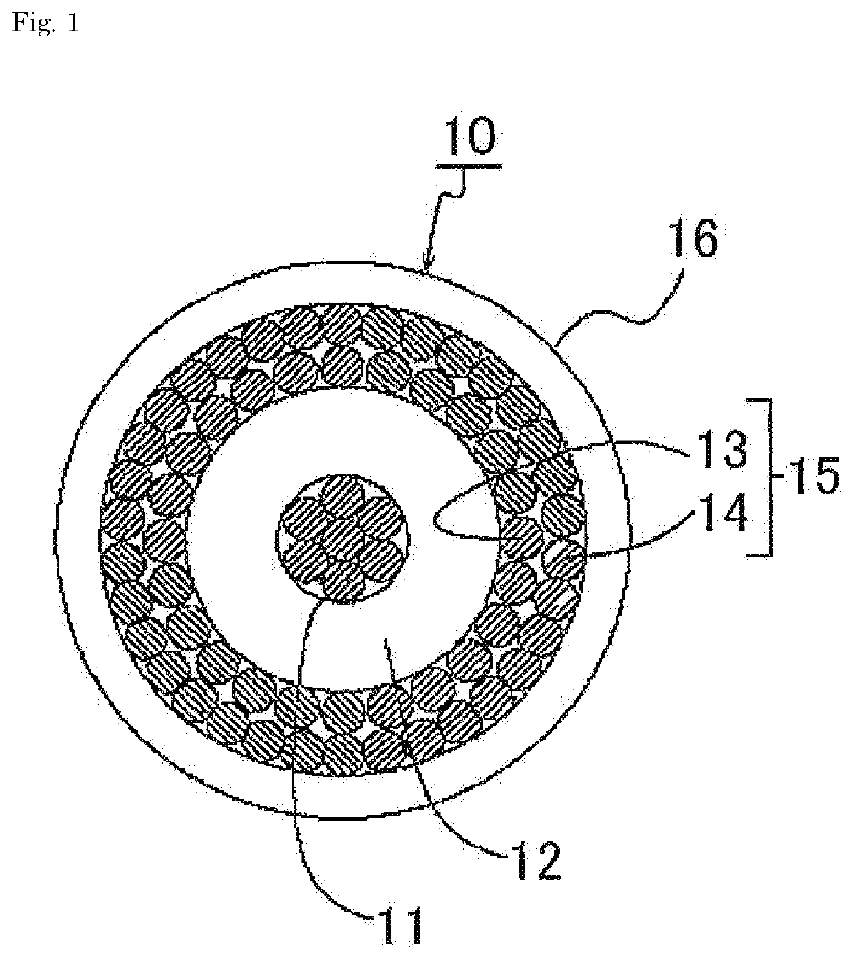
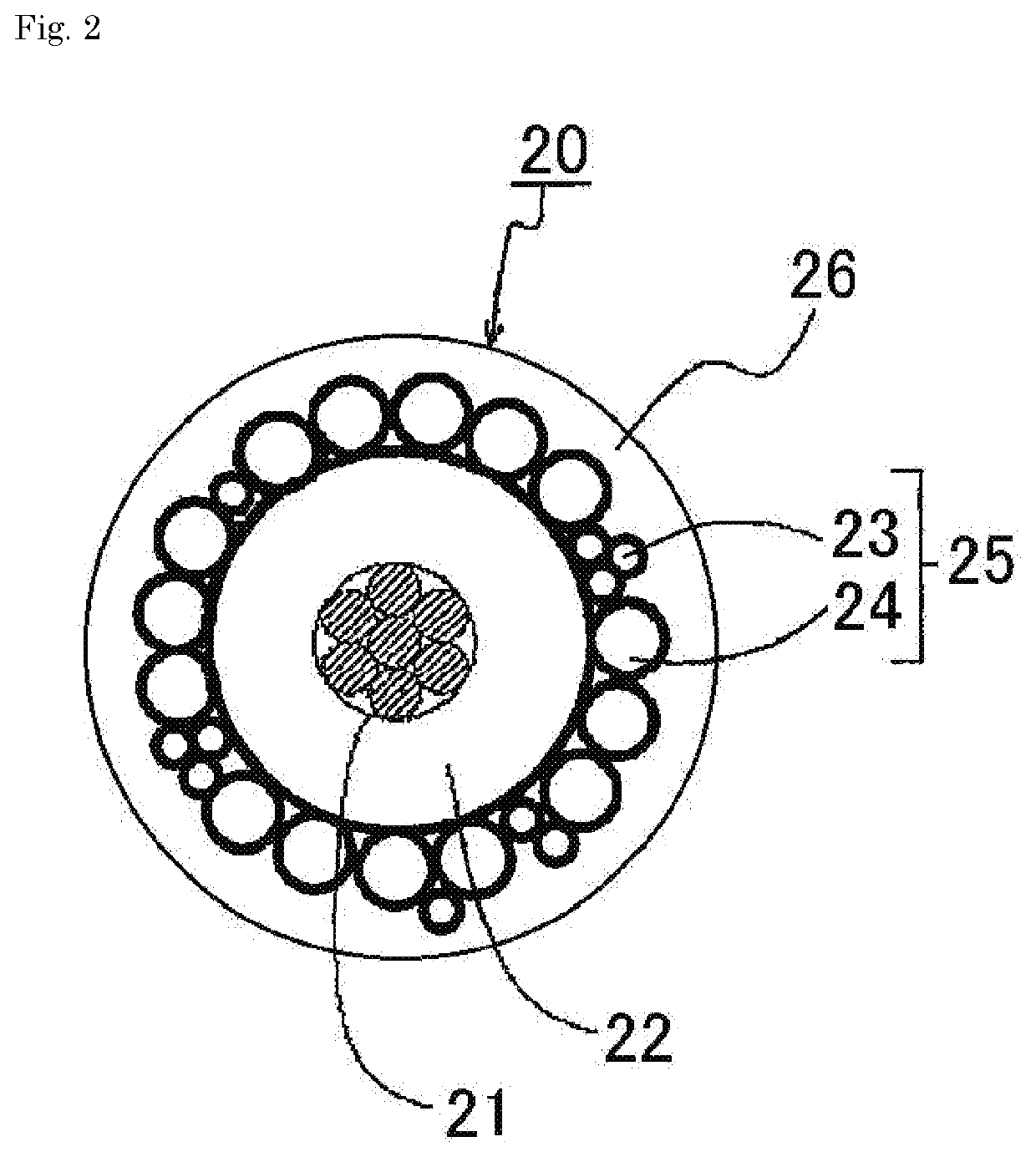
[0053]As the center conductor, a AWG40 conductor (a conductor having an outer diameter of 0.09 mm by twisting seven silver-plated copper-alloy strands having an outer diameter of 0.03 mm) was used, and as the insulator layer, PFA was extruded to a thickness of 0.075 mm to obtain an outer diameter of 0.24 mm. The exterior of the insulation layer was rolled horizontally by combining 24 silver-coated soft copper lines having a strand-diameter of 0.03 mm and 8 silver-coated hard copper lines having a strand-diameter of 0.021 mm, and passed through a 0.31 mm die to form an outer conductor. A coaxial cable was produced by extruding 0.03 mm thick PFA onto the outer circumference of the outer conductor. This coaxial cable was used to make a two-core parallel cable, and the far-end crosstalk was measured.

example 2

[0054]A coaxial cable was prepared in the same manner as in Example 1 except that 19 silver-plated soft copper wires having a strand-diameter of 0.04 mm and 8 silver-plated hard copper wires having a strand-diameter of 0.021 mm were mixed and wound laterally as the outer conductor, and a two-core parallel cable was prepared to measure the far-end crosstalk.


PUM

PropertyMeasurementUnit
frequencyaaaaaaaaaa
frequencyaaaaaaaaaa
outer diameteraaaaaaaaaa

Abstract

The present invention relates to a coaxial cable, and particularly to a small-diameter coaxial cable for use in frequency bands of 100 MHz or more. The present invention addresses the problem of providing a coaxial cable which has excellent flexibility, a small outer diameter, and excellent shielding characteristics. The problem is solved by a coaxial cable having an outer conductor which is formed by mixing and laterally winding strands in the same direction, the strands having an outer diameter difference of not less than 10% between a large-diameter strand having a maximum outer diameter and a small-diameter strand having a minimum outer diameter.

Description

CROSS-REFERENCE TO RELATED APPLICATIONS[0001]This application is the United States national phase of International Application No. PCT / JP2018 / 004095 filed Feb. 6, 2018, and claims priority to Japanese Patent Application No. 2017-023662 filed Feb. 10, 2017, the disclosures of which are hereby incorporated by reference in their entirety.BACKGROUND OF THE INVENTION1. Field of the Invention[0002]The present invention relates to a coaxial cable, and more particularly, to a coaxial cable having a small diameter, which is used in a band having a frequency of 100 MHz or more, in particular, in a band having a frequency of 1 GHz or more.2. Description of Related Art[0003]It is known to use a fine coaxial cable for transmitting a high-frequency signal through a fine transmission line, such as a signal line of a medical cable such as an endoscope or an ultrasonic probe cable, or a signal line for controlling a notebook computer, a game machine, or a robot. In recent years, miniaturization of e...

Claims


Application Information

Patent Timeline
Patent Type & Authority Patents(United States)
IPC IPC(8): H01B11/18
CPCH01B11/1878H01B11/1813H01B11/1033H01B11/18
Inventor HIRAOKA, DAIKIADACHI, TOMOHIROFURUHASHI, FUMIYUKI
Owner JUNKOSHA
Why Eureka
Try Eureka