Direct-read meter capable of eliminating magnetic interference of adjacent rotating wheels

a direct-read, rotating wheel technology, applied in the field of magnetic sensors, can solve the problems of increasing the complexity of the magnetic field distribution, increasing the manufacturing cost of the read-only type water meter, and introducing non-linear components, so as to achieve the effect of precise information of rotation angl

Active Publication Date: 2020-10-06
MULTIDIMENSION TECH CO LTD
View PDF10 Cites 0 Cited by
  • Summary
  • Abstract
  • Description
  • Claims
  • Application Information

AI Technical Summary

Benefits of technology

[0006]In order to solve the problem of mutual interference between the permanent magnet rotating wheels, the present invention proposes a direct-read meter capable of eliminating magnetic interference of adjacent rotating wheels, which converts a raw magnetic field measured by a magnetic sensor to a correction magnetic field through an algorithm without relying on increasing magnetic shielding, and implements exclusion of interfering magnetic fields according to output signals thereof, thus obtaining precise information of rotation angles.

Problems solved by technology

However, a direct-read water meter of a system including multiple permanent magnet rotating wheels has the following problems:
As the distance between the permanent magnet rotating wheels cannot be too far, a magnetic sensor, in addition to detecting the magnetic field from the corresponding permanent magnet rotating wheel, are also subject to interfering magnetic fields from other permanent magnet rotating wheels.
In this way, on one hand, the manufacturing cost of the read-only type water meter is increased, and on the other hand, a magnetic circuit of the system may be changed, which increases complexity of distribution of the magnetic fields and introduces non-linear components.

Method used


Image

  • Direct-read meter capable of eliminating magnetic interference of adjacent rotating wheels
  • Direct-read meter capable of eliminating magnetic interference of adjacent rotating wheels
  • Direct-read meter capable of eliminating magnetic interference of adjacent rotating wheels

Examples


embodiment i

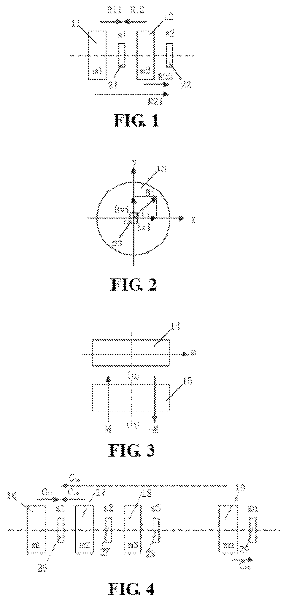
[0039]FIG. 1 is the simplest situation that the system is a direct-read meter including two permanent magnet rotating wheels m1 (i.e., 11) and m2 (i.e., 12) and corresponding magnetic angle sensors s1 (i.e., 21) and s2 (i.e., 22). A position relationship between one permanent magnet rotating wheel 13 and a magnetic angle sensor 23 and a relationship of magnetic fields produced by the permanent magnet rotating wheel 13 at the magnetic angle sensor 23 are as shown in FIG. 2, wherein Bi is a rotating magnetic field and can be decomposed into X and Y magnetic field components Bxi and Byi that are perpendicular to each other. In the figure, the magnetic angle sensor 23 is near a center shaft of the permanent magnet rotating wheel 13. As a matter of fact, the magnetic angle sensor 23 may also be located in another operating area deviating from the axis. FIG. 3 shows two magnetization states of the permanent magnet rotating wheel, one of which is as shown in FIG. 3(a), i.e., the permanent ...

embodiment ii

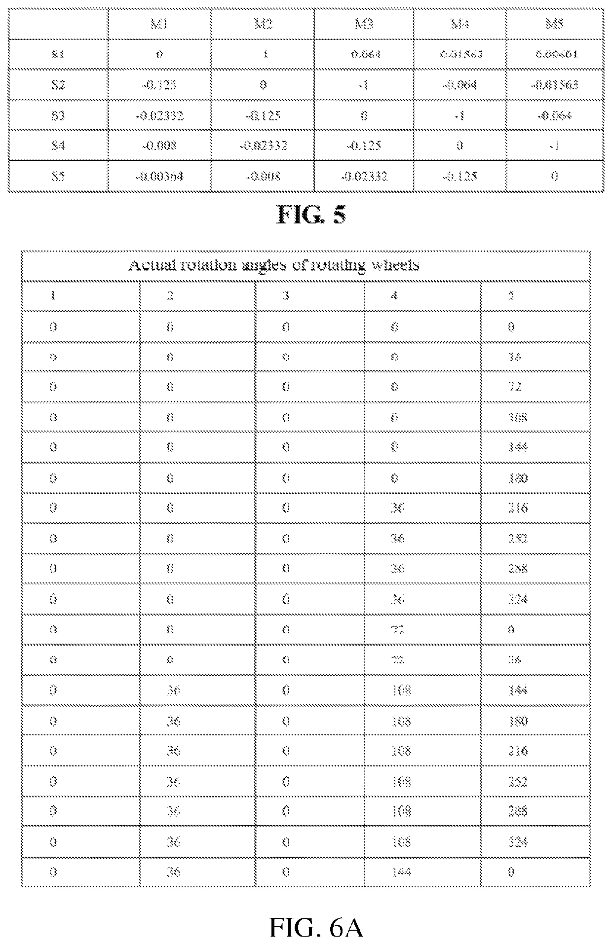
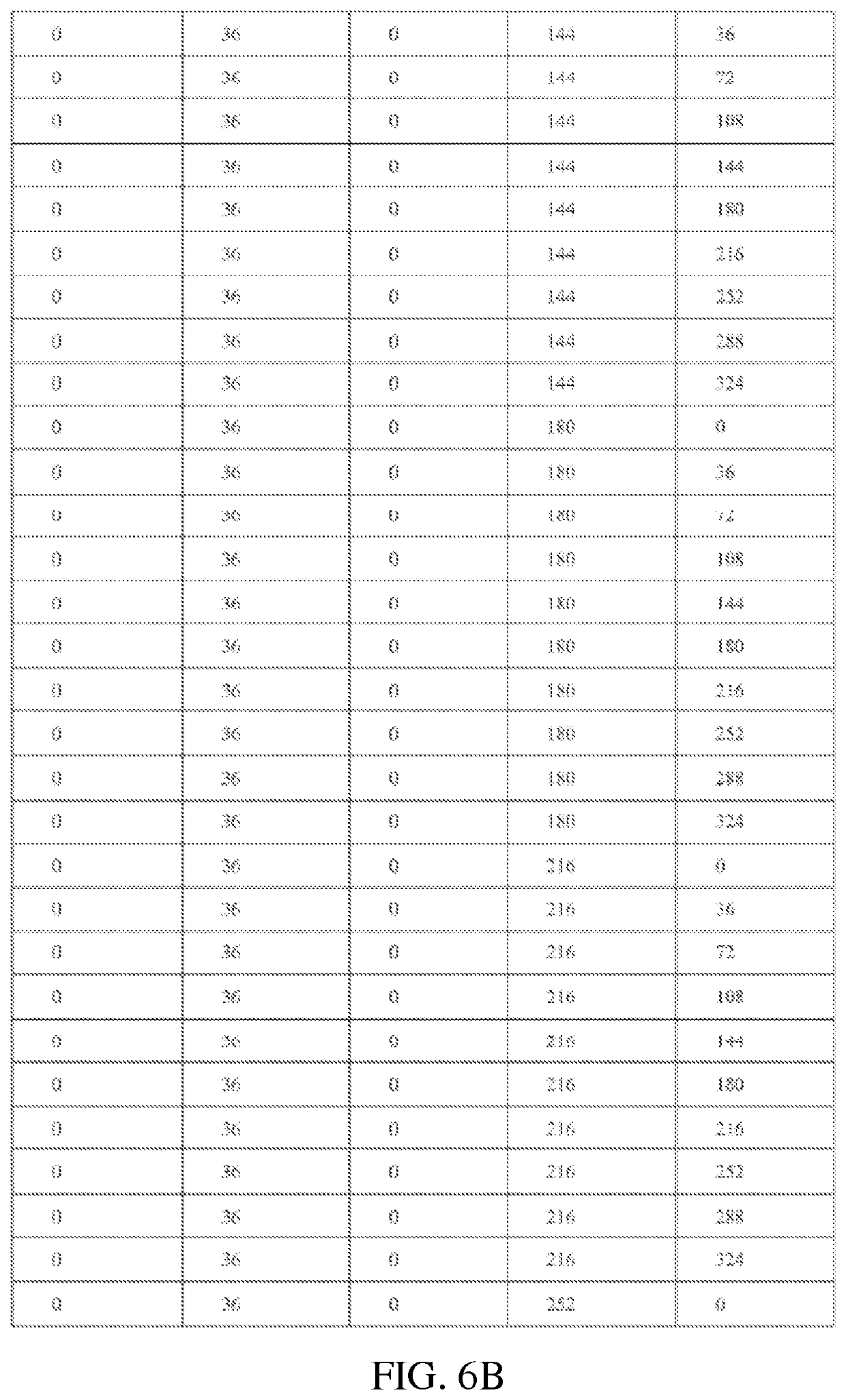
[0069]The above algorithm of eliminating magnetic interference is checked in the following by taking a direct-read meter including 5 permanent magnet rotating wheels and 5 magnetic angle sensors as an example. That is, when N=5, a correction factor matrix thereof is as shown in FIG. 5. FIG. 6 shows rotation angles of permanent magnet rotating wheels of a system including 5 permanent magnet rotating wheels and 5 magnetic angle sensors. FIG. 7 shows raw output signals corresponding to a system including 5 permanent magnet rotating wheels and 5 magnetic angle sensors. FIG. 8 shows calculation values of raw rotation angles of a system including 5 permanent magnet rotating wheels and 5 magnetic angle sensors. FIG. 9 shows corrected output signals of a system including 5 permanent magnet rotating wheels and 5 magnetic angle sensors. FIG. 10 shows corrected rotation angles and errors of magnet rotating wheels of a system including 5 permanent magnet rotating wheels and 5 magnetic angle sen...

embodiment iii

[0070]FIG. 12 shows a direct-read meter capable of eliminating magnetic interference of adjacent rotating wheels, which includes N permanent magnet rotating wheels 31, 32 to 3N and N corresponding biaxial angle sensors, i.e., 41, 42 to 4N (wherein the permanent magnet rotating wheels and the biaxial angle sensors are in a one-to-one corresponding relationship), and includes a sampling element 51 capable of high-speed sampling all the raw output sine / cosine signals of the N biaxial magnetic angle sensors to form a N*1 raw signal matrix [V / Vp]k(i)raw, a storage element 53 capable of storing an N*N correction matrix [Cij], and a computation element 52 that performs arithmetical operation [V / Vp]kcorr(i)=[V / Vp]k(i)raw−sum{C(i, j)*[V / Vp]k(j)raw} to eliminate the interfering magnetic field. In this embodiment, the sampling element is an A / D converter, the computation element is a MCU microprocessor, and the storage element 53 is a memory that may be arranged outside the MCU or arranged ins...


PUM

PropertyMeasurementUnit
angle erroraaaaaaaaaa

Abstract

A direct-read meter capable of eliminating magnetic interference of adjacent rotating wheels, comprising N coaxial rotating wheel permanent magnets and corresponding magnetic angle sensors, a sampling element, a storage element, and a computation element. The magnetic angle sensors sense a linear superposition of the magnetic field from the intended permanent magnet rotating wheel and the interfering magnetic fields from the other rotating wheel permanent magnets. The sampling element samples the output signals of the N magnetic angle sensors to form a N*1 raw signal matrix [V / Vp]k(i)raw. The storage element stores an N*N correction matrix [Cij]; and the computation element computes the correction signal matrix [V / Vp]kcorr(i)=[V / Vp]k(i)raw−sum{C(i, j)*[V / Vp]k(j)raw}, thus eliminating the interfering magnetic field and permitting calculation of the rotation angle of the rotating wheel permanent magnets. This direct-read meter has the advantages of simple calculation, high precision, and elimination of the need for magnetic shielding.

Description

PRIORITY CLAIM TO RELATED APPLICATIONS[0001]This application is a U.S. national stage application filed under 35 U.S.C. § 371 from International Application Serial No. PCT / CN2016 / 070543, which was filed 11 Jan. 2016, and published as WO2016 / 112829 on 21 Jul. 2016, and which claims priority to Chinese Application No. 201520024560.0, filed 14 Jan. 2015, and to Chinese Application No. 201510029996.3, filed 21 Jan. 2015, which applications and publication are incorporated by reference as if reproduced herein and made a part hereof in their entirety, and the benefit of priority of each of which is claimed herein.TECHNICAL FIELD[0002]The present invention relates to the field of magnetic sensors, and in particular, to a direct-read meter capable of eliminating magnetic interference of adjacent rotating wheels.BACKGROUND ART[0003]A direct-read electronic flow meter includes multiple coaxial rotating wheels. There is a set transmission ratio relationship between the rotating wheels. The tot...

Claims


Application Information

Patent Timeline
Patent Type & Authority Patents(United States)
IPC IPC(8): G01F25/00G01F1/60G01F1/58G01F15/00G01F15/06
CPCG01F25/0007G01F15/066G01F1/60G01F1/586G01F15/00G01F25/10
Inventor DEAK, JAMES GEZAZHOU, ZHIMIN
Owner MULTIDIMENSION TECH CO LTD
Why Eureka
Try Eureka