
Offshore positioning system and method

a positioning system and positioning system technology, applied in the field of offshore positioning system and method, can solve the problems of frequent attention, difficulty in positioning such sensors, and difficulty in engineering operations at sea, and achieve the effects of reducing difficulty, facilitating evaluation of results, and reducing difficulty

Active Publication Date: 2020-10-06
FNV IP BV
View PDF21 Cites 0 Cited by
  • Summary
  • Abstract
  • Description
  • Claims
  • Application Information

AI Technical Summary

Benefits of technology

[0012]According to a yet further advantage of the invention, the system also comprises a calibration facility. This may be arranged to calibrate the total body-frame roll axis error of a respective imaging device and the attitude sensing arrangement. In this context, total body-frame roll is intended to refer to the combined error due to both the attitude sensor accuracy and any misalignment between the mounting of the camera and attitude sensor. This may be accomplished by taking an image of the horizon, which by definition must be horizontal. Frequent self-checks can be carried out, which have the advantage that a device can be verified to work correctly in the marine environment. Distortions arising from e.g. shipment of the unit, resulting in increased measurement errors, can be easily detected using such a method.
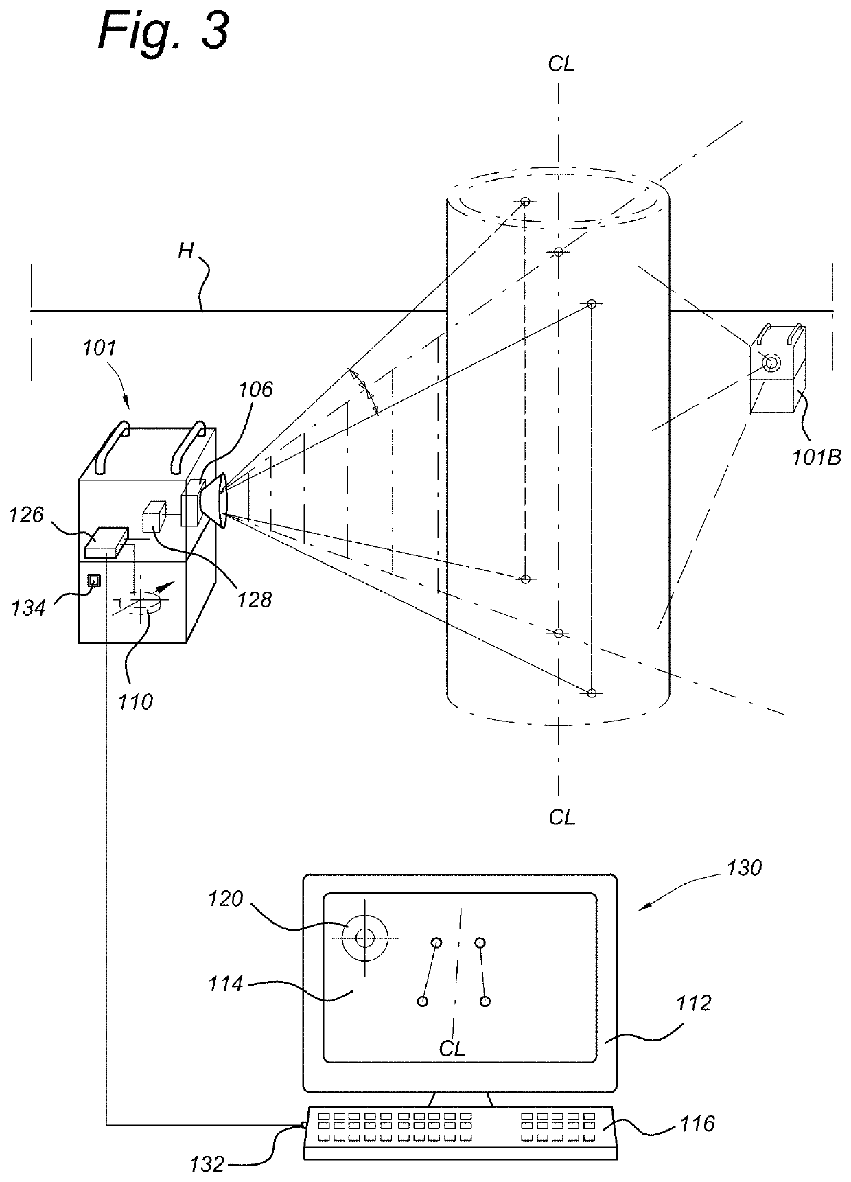
[0013]According to a still further aspect of the invention, the system allows measurement and determination of the attitude in real time. There may also be an attitude display providing a real-time representation of the attitude of the object. One particularly convenient display is in the form of a sight glass or spirit level, allowing an operator to monitor deviation of the object from a desired attitude. The system may also or alternatively comprise a user interface and an image display. In one convenient form, the image processing system may be arranged such that a user can manually pick a portion of an image of the object on the display for use in determining the attitude of the object. The portion of the object may be a characteristic edge or marking on the object and picking may take place using a mouse or similar pointer to identify the portion on the image display. Additional software may be provided for locking the image based on image recognition of the characteristics of the portion. This can be of use in situations where the object becomes partially obscured and a human operator may more reliably identify the relevant portions.
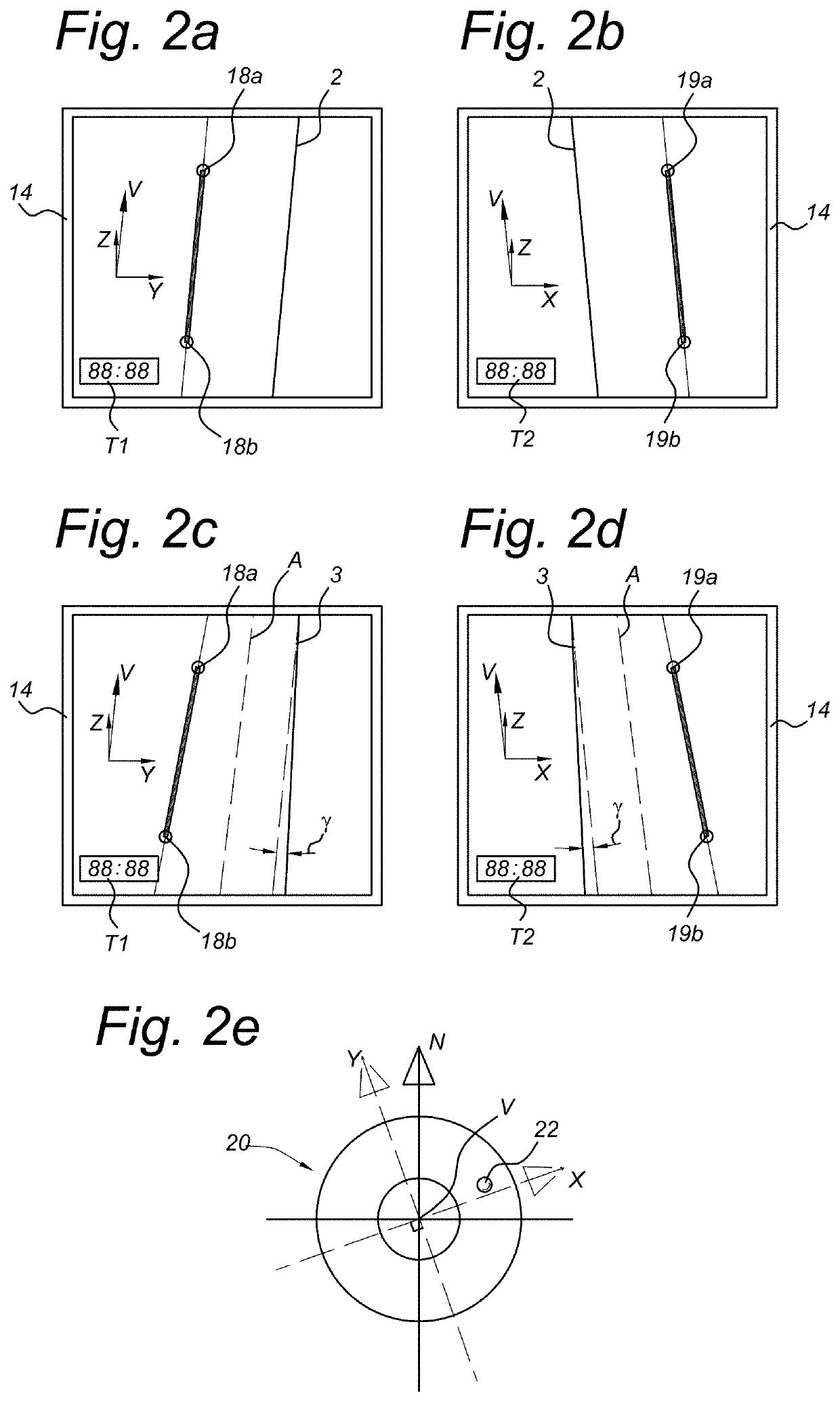
[0014]Although the system may be used for determining the orientation or attitude of many alternative objects, it is particularly suitable for use in determining the verticality of a pile, more specifically the sort of pile or monopile used for offshore wind turbine generators. In one embodiment of the system, the image processing system is arranged to: determine left and right borders of the pile from the first imaging device and identify a location of the plane therebetween that passes through the first imaging device; determine left and right borders of the pile from the second imaging device and identify a location of the plane therebetween that passes through the second imaging device; and combine the location of the planes from both the first and second imaging devices to determine the attitude of the axis of the pile. Assuming that the pile is rotationally symmetric, the mid-plane between the edges will identify the central axis irrespective of the direction of viewing. This makes it considerably easier to evaluate the results, as it is independent of the distance between the imaging devices and the pile. It is also applicable even when the pile tapers.
[0015]The invention also relates to a device for measuring an attitude of an object in a fixed frame of reference from a moving frame of reference, the device comprising: an imaging device for producing image data for the object; an attitude sensor for determining an attitude of the imaging device with respect to the fixed frame of reference at the time the image is taken and for generating attitude data; and a communication port for transmitting data to a data processing system for determining or displaying the attitude of the object. In a simple form, the attitude sensor may be a one- or two-axis attitude sensor without north-seeking capability. It will be understood that north-seeking devices are considerably more expensive and a simple non north-seeking device may be more than adequate for many purposes, especially when used e.g. in combination with a ship's north-seeking facility or with additional GPS positioning. A more complex embodiment of the invention provides a single device in which the imaging device and a north-seeking attitude sensor are integrated. Such a device is extremely versatile and can in fact be moved to a given location and immediately provide relevant input for determining the attitude of the object. This may be the case, even when the absolute position is unknown, based merely on the attitude information. It will be understood that the data transmitted may be the image data and the attitude data. In this case, the remote data processing system may include an image processing system for analyzing and combining the image data and attitude data to determine the attitude of the object as described above. Alternatively, an image processing system may be provided in the device and the transmitted data may comprise partially processed data related to the attitude of the object. The device may also include a local image display and user interface.
[0016]According to an embodiment, the device may comprise a clock, arranged to time stamp the image data relative to the attitude data. The clock may be a local clock or may be a clock signal derived from an external source such as the data processing system or a satellite navigation system. Stamping the image and attitude data in an accurate manner is of importance in ensuring that they are coherent, especially when analysis takes place subsequently. The clock or time stamp facility may be part of a real-time signal multiplexer that combines the attitude data and the image data.
[0017]Most preferably, the device is portable and the imaging device and the attitude sensor are fixed to each other to prevent relative movement. By portable, it is understood that the device is of a size and weight to be easily carried and set up by one person. It will be understood that such a device may even be used alone to provide measurements from two directions by moving from a first position to a second position. Such a device could be mounted on a separate vessel, movable with respect to the object being measured.

Problems solved by technology

Engineering operations at sea often involve considerable difficulty due to the constant movement of the waves.
Positioning of such sensors can be difficult and they may require frequent attention e.g. on passing joints on the cable.
They may also be easily damaged, especially when laying multiple cables and at present are not applicable to all situations.

Method used


Image

  • Offshore positioning system and method
  • Offshore positioning system and method
  • Offshore positioning system and method

Examples


first embodiment

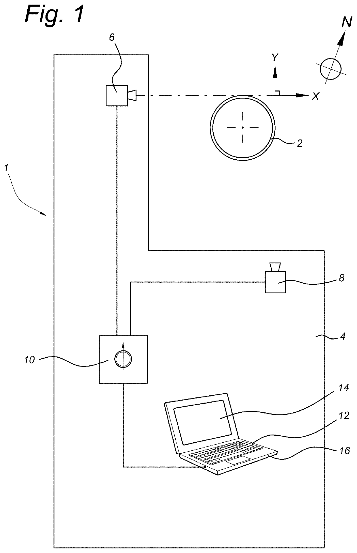
[0031]FIG. 1 shows a schematic view of a system 1 for measuring the attitude of a monopile 2 according to the invention. The system 1 is mounted upon a barge 4, which is being used for installation of the monopile 2. Cranes and pile-driving equipment is not shown for the sake of convenience but may be otherwise conventional.

[0032]The system 1 comprises a first camera 6 and a second camera 8 mounted on the barge 4 within view of the monopile 2 and directed towards it. The cameras 6, 8 are mounted to view the monopile from orthogonal directions i.e. the lines of sight from the respective camera to the monopile are perpendicular to each other. As will be understood by the skilled person in the following, these directions need not be perfectly perpendicular. In the present embodiment, the first camera 6 is aimed along a left hand edge of the monopile 2 and is aligned across the barge 4 in a direction denoted X. The second camera 8 is aimed at a right hand edge of the monopile and direct...

second embodiment

[0045]According to FIG. 4, cable-lay vessel 204 is provided at its stern with a stinger or chute 211 over which cable 202 is deployed to the seabed. Attitude measuring devices 201 according to the invention are mounted overboard at the stern. The attitude measuring devices 201 are similar to the devices 101 of the second embodiment except that they incorporate attitude sensors without north-seeking capability. Cameras 206 are directed towards the cable 202 at the point where this leaves the chute 211. Data acquisition takes place as in the previous embodiments, with image data and attitude data being time stamped and processed to determine the attitude of the cable 202 at its point of departure from the vessel 204 in the geodetic frame of reference. FIG. 5 is a schematic view of the cable 202 at this point, indicating the geodetic vertical direction V and the horizontal plane H. The angle of the cable 202 with respect to its orthogonal projection onto the horizontal plane H is given...


PUM


Abstract

A system for measuring the attitude of an object in a fixed frame of reference from a moving frame of reference, comprising a first imaging device for producing image data for the object from a first direction, a second imaging device for producing image data for the object from a second direction having a component perpendicular to the first direction and an attitude sensing arrangement for determining an attitude of the first and second imaging devices with respect to the fixed frame of reference at the time the respective images are taken and for generating attitude data. An image processing system analyses and combines the respective image data and attitude data to determine the attitude of the object. The system is particularly useful for determining attitude of offshore piles during piling operations or for monitoring the departure angles of pipes and cables during laying thereof.

Description

BACKGROUNDField of the Invention[0001]The present invention relates to devices and systems for determining an attitude of an object in a fixed frame of reference by observations from a moving frame of reference and more particularly to a system capable of accurately measuring the verticality of a pile or similar object from a floating platform or vessel. The invention also relates to a method of performing such measurements.Description of the Related Art[0002]Engineering operations at sea often involve considerable difficulty due to the constant movement of the waves. This is especially the case when accuracy is required in performing measurements. For a vessel at sea, measurements may be made in a fixed frame of reference relative to the earth or in a moving frame of reference relative to the vessel.[0003]One situation where measurements in the absolute frame of reference are relevant is in the installation of fixed structures from a floating platform or vessel. In recent years lar...

Claims


Application Information

Patent Timeline
Patent Type & Authority Patents(United States)
IPC IPC(8): G06T7/70B63B79/00G01C9/00H04N7/18B63B35/04G01B11/27G01B11/26
CPCG06T7/70G01B11/26G01C9/00H04N7/181B63B35/04G01B11/272B63B79/00G01C9/06G01C2009/066
Inventor BOOIJ, OLAFNEJADASL, FATEMEH KARIMISCHIPPERS, EVERTWOUTERS, HENDRIK
Owner FNV IP BV
Learn More