Lift device for dust collection box of wood working machine

Active Publication Date: 2020-09-29
YU HSI HUI
View PDF5 Cites 5 Cited by
  • Summary
  • Abstract
  • Description
  • Claims
  • Application Information

AI Technical Summary

Benefits of technology

The present invention provides a lift device that helps users install and remove a dust collection box easily. It also maintains the box at a safe height to prevent accidents. Additionally, the lift device allows for the removal of the box with a single person.

Problems solved by technology

It is difficult for doing this by only one person, because the dust collection box 4 may fall down to the floor.

Method used


Image

  • Lift device for dust collection box of wood working machine
  • Lift device for dust collection box of wood working machine
  • Lift device for dust collection box of wood working machine

Examples


Embodiment Construction

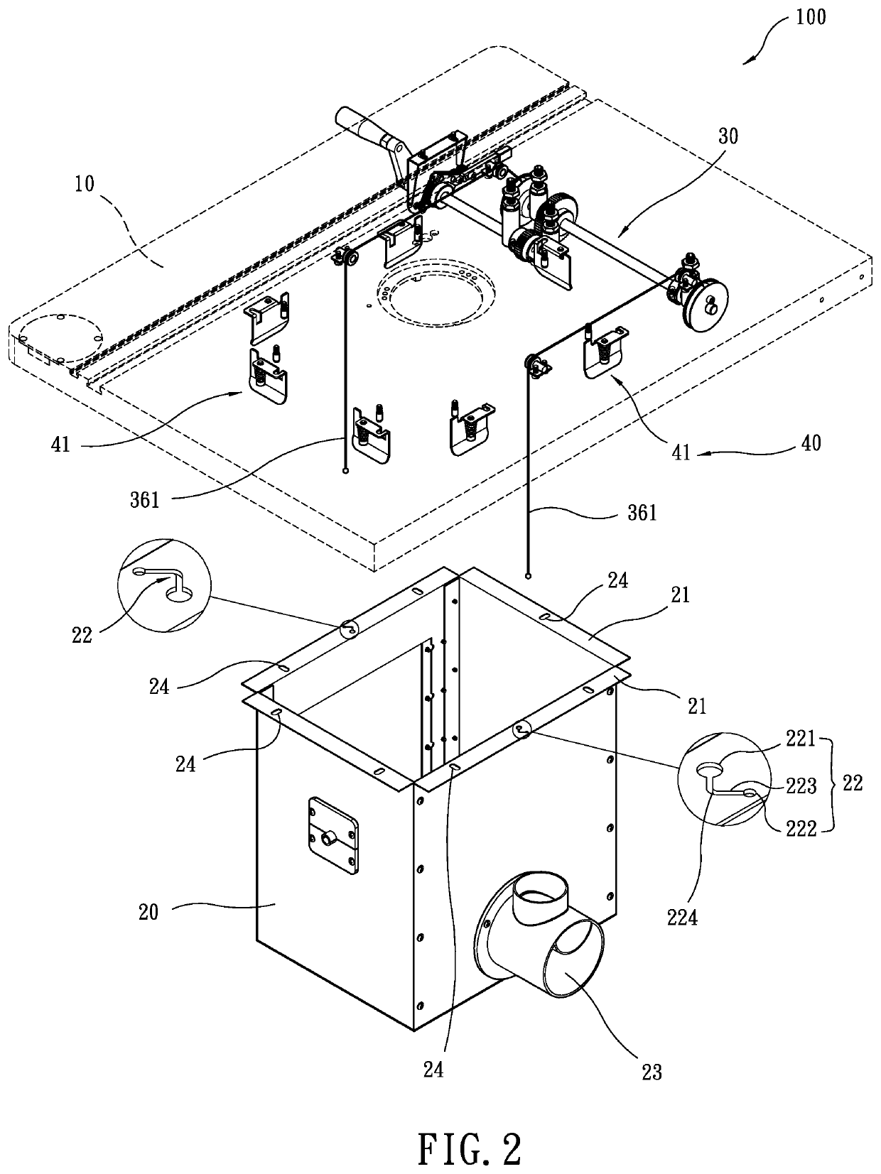
[0024]Referring to FIGS. 2 to 13, the lift device 100 for a dust collection box of a wood working machine of the present invention comprises a working table 10, a dust collection box 20, a lift device 30 and a positioning device 40.

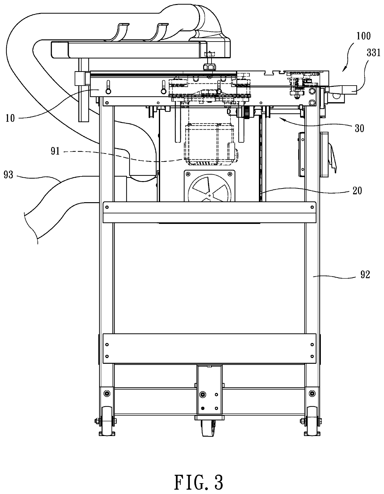
[0025]As shown in FIGS. 2 and 3, a machining device 91 is installed to the working table 10 so as to proceed machining to objects on the working table 10. The working table 10 is supported on a base 92 which is put on the floor so that the working table 10 is located at a certain height.

[0026]As shown in FIG. 2, the dust collection box 20 is a box with an open top and multiple flanges 21 respectively extend from the top of four sidewalls of the dust collection box 20. Each of two opposite flanges 21 has at least two connection portions 22 formed therein which are located symmetrically to each other. Each of the flanges 21 includes at least one hole 24 which is an elongate hole. Each of the at least two connection portions 22 of the dust collection box 20 ...


PUM


Abstract

A lift device for a dust collection box of a wood working machine includes a driving shaft unit, a passive shaft unit, a rotary unit, a break unit, a pulley unit and a cable unit. The driving shaft unit and the passive shaft unit are connected to the underside of the working table. The driving shaft unit includes a first gear and a second gear. The passive shaft unit includes a third gear which is engaged with the second gear. The rotary unit is connected to the driving shaft unit to rotate the driving shaft. The break unit is pviotable between a break position and a loose position. When the break unit is at the break position, the break unit prevents the driving shaft from self-rotating. The lift device lifted or lowers the dust collection box by cooperation of the pulley unit and the cable unit the lift device.

Description

BACKGROUND OF THE INVENTION1. Fields of the Invention[0001]The present invention relates to a lift device for lifting or lowering a dust collection box relative to the working table of a wood working machine.2. Descriptions of Related Art[0002]The conventional wood working machine 1 as disclosed in FIG. 1, includes a working table 2 and a machining device 3 is installed to the working table 2 so as to proceed machining tasks to objects.[0003]During machining the objects on the working table 2, wood powder, debris and the like is generated and floats in the air. Therefore, a suction device (not shown) is used to suck the wood powder and debris. Yet the wood powder and debris around the machining device 3 cannot be sucked by the suction device, and a dust collection box 4 is used to collect the wood powder and debris around the machining device 3. A vacuum machine 5 remove the powder and debris from the dust collection box 4 to keep clean around the machining device 3.[0004]The dust c...

Claims


Application Information

Patent Timeline
IPC IPC(8): B66D1/04B23Q11/00
CPCB66D1/04B23Q11/0067B66D2700/026B23Q11/0046B27C5/00B27C5/02B27C9/02
Inventor YU, HSI-HUI
Owner YU HSI HUI
Why Eureka
Try Eureka