
Pedal powered vehicle

a pedal-powered, tricycle technology, applied in the direction of machines/engines, cycles, transportation and packaging, etc., can solve the problems of quadricycles undesired excessive vehicle speed, waste or discourage the operator's ability to provide additional pedaling

Active Publication Date: 2020-09-29
HOWE THOMAS M
View PDF53 Cites 0 Cited by
  • Summary
  • Abstract
  • Description
  • Claims
  • Application Information

AI Technical Summary

Benefits of technology

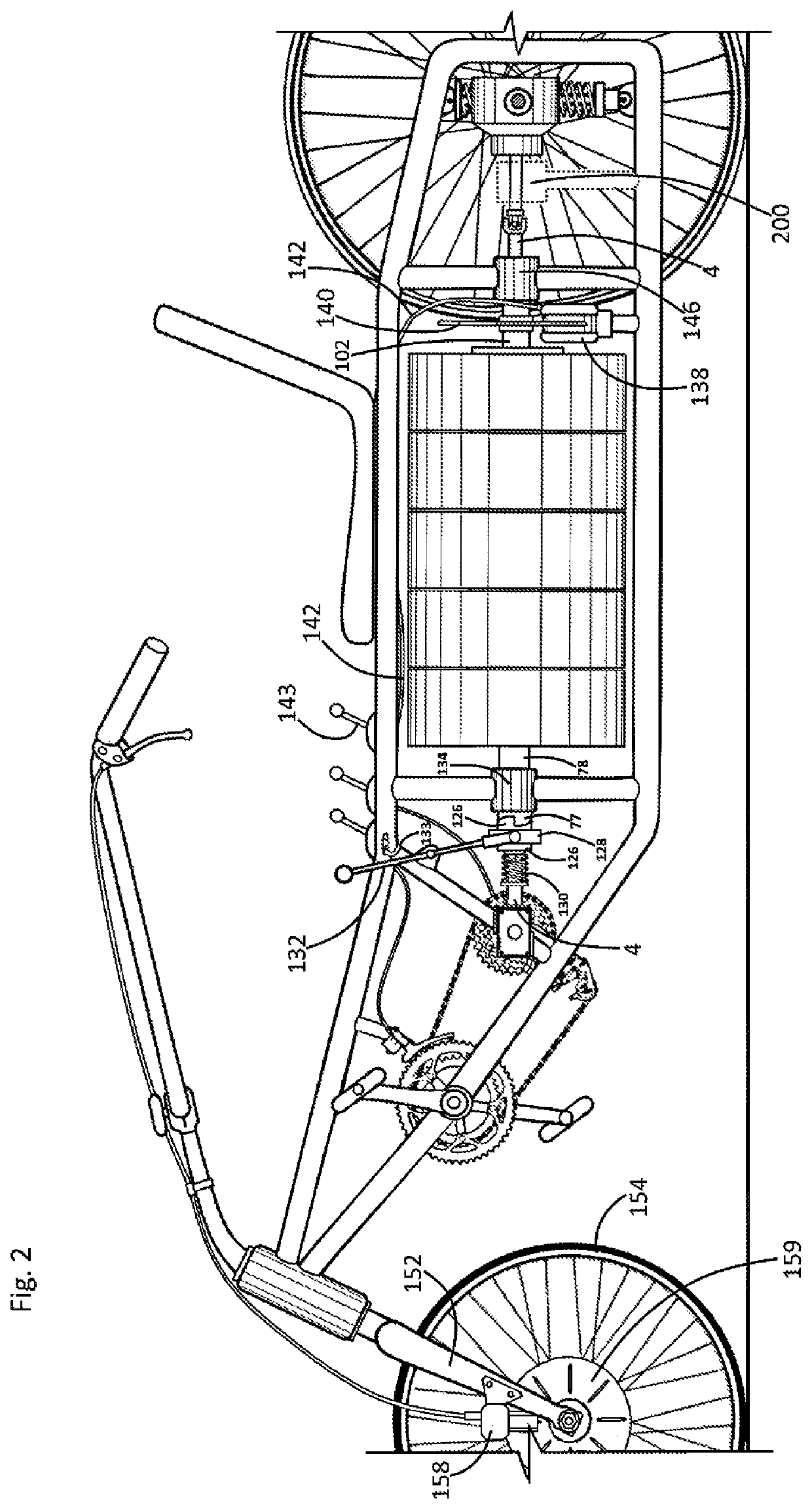
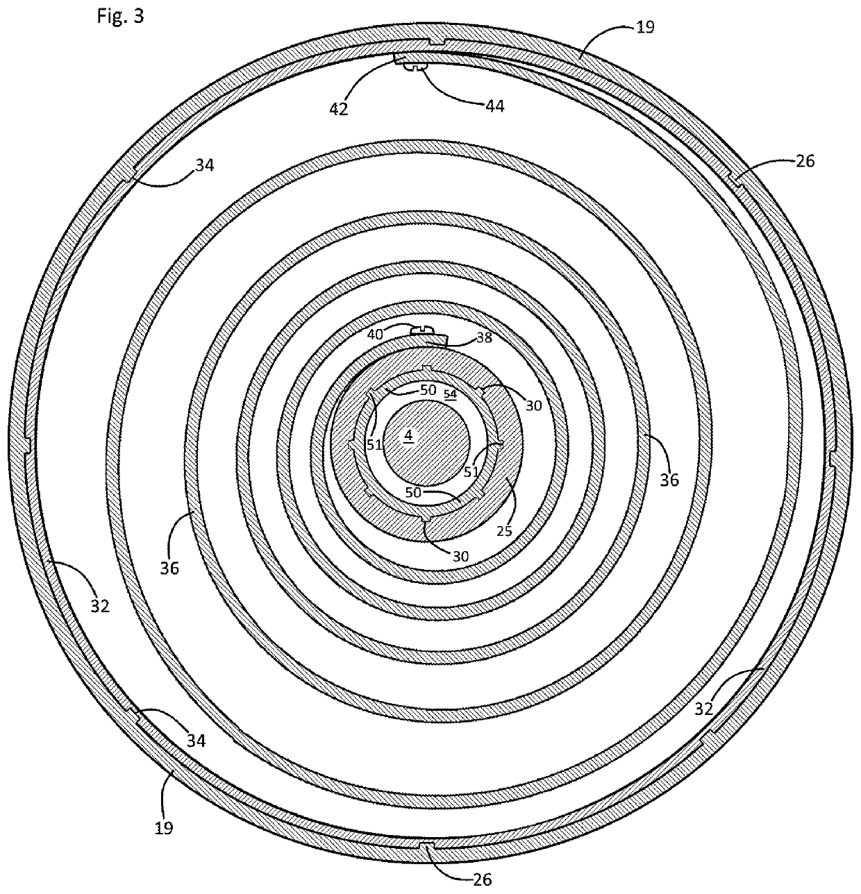
[0017]The above process of successively downshifting for continued pedal powered winding of the spring sub-segments may continue until each of the spiral spring's progressively tensioned segments is fully wound. At the spiral spring's fully wound state, it carries a maximum level of stored or potential spring energy while the spring's rotary power input end remains rotationally fixed with respect to the frame by the invention's first one way bearing component, and while the invention's rotary output end is similarly rotationally fixed by the invention's engaged brake. A subsequent release of the brake advantageously allows the stored rotary power of the spring to translate to the rotary power output end of the drive shaft via rotating engagement of the invention's second one way clutch. Thus, the instant inventive vehicle advantageously allows excess pedaling energy to be accumulated during level or downhill road travel, and to be subsequently utilized for assistance in uphill travel.

Problems solved by technology

However, in many circumstances such an application of additional pedaling power only results in the production of an undesirably excessive vehicle speed.
Accordingly, typical and conventional pedal powered tricycle and quadricycles undesirably waste or discourage the operator's capability of providing additional pedaling exertion and power during level or downhill travel.

Method used


Image

  • Pedal powered vehicle
  • Pedal powered vehicle
  • Pedal powered vehicle

Examples


Embodiment Construction

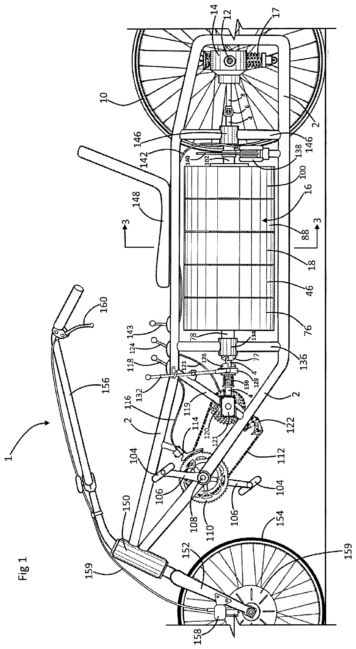
[0024]Referring now to the drawings, and in particular to Drawing FIG. 1, a preferred embodiment of the instant inventive pedal powered vehicle is referred to generally by Reference Arrow 1. The vehicle 1, as drawn in an exemplary and representational fashion, constitutes a tricycle having a single steerable front wheel 154 and a rearward powered or driven wheel 10. For purposes of understanding of structures within the view, the vehicle's left rear stabilizing wheel is not drawn, and the vehicle's left lateral axle 12 is shown cut off.

[0025]The vehicle 1 has a tubular support frame 2 whose forward end includes a steering hub 150 which rotatably supports a front fork 152 and left and right handlebars 156. A caliper brake 158 and disk 159 assembly which is actuated by a hand brake lever 160 and an actuator cable 159 controls rotation of the front wheel 154 for braking of the vehicle 1.

[0026]A drive shaft 4 extends longitudinally along the frame 2, such drive shaft being supported upo...


PUM


Abstract

A wheeled vehicle incorporating a frame; a drive shaft mounted upon the frame, the drive shaft having rotary power input and output ends; a drive wheel mounted upon the frame; a rotary power output linkage operatively interconnecting the drive shaft's output end and the drive wheel; rotary power pedals mounted upon the frame; a rotary power input linkage operatively interconnecting the drive shaft's input end and the rotary power pedals; a spiral spring having a rotary power input end and a rotary power output end, the spiral spring being mounted over the drive shaft; a clutch and one way bearing combination for anchoring the spiral spring's rotary power input end upon the drive shaft and upon the frame; and a one way bearing and brake combination for alternatively anchoring the spiral spring's rotary power output end upon the drive shaft and upon the frame.

Description

FIELD OF THE INVENTION[0001]This invention relates to pedal powered tricycles, quadricycles, and the like. More particularly, this invention relates to such vehicles which are specially adapted for storing excess pedal powered rotational torque as potential spring energy, and for selectively releasing such stored potential energy for subsequent assistance in propulsion of the vehicle.BACKGROUND OF THE INVENTION[0002]In use of commonly known pedal powered tricycles and quadricycles, such vehicles are often driven and propelled over level road surfaces or along downhill road surfaces. During passages of such vehicles over such surfaces, an operator pedaling the vehicle is commonly able to maintain a desired speed through an application of a minimal or small level of pedaling exertion. During such level or downhill operation of such conventional pedal powered vehicle, the operator typically is capable of applying pedaling power to the vehicle at a level which exceeds that which is nece...

Claims


Application Information

Patent Timeline
Patent Type & Authority Patents(United States)
IPC IPC(8): B62M1/10F03G1/02B62M1/36B62K5/003B62K5/02F03G1/08
CPCB62M1/10B62M1/36F03G1/08B62K5/02B62M1/105B62K5/003F03G1/02F03G2730/01F03G1/022
Inventor HOWE, THOMAS M.
Owner HOWE THOMAS M
Learn More