
Method and system for obtaining angle-doppler signatures in MIMO radars

a technology of mimo radar and signature, applied in the field of wireless detection of objects using mimo radar, can solve the problems of system design, approach works, and angular resolution is physically limited by the total antenna array size, and achieve the effects of reducing angle-doppler ambiguity, less antenna elements, and improving target detection discrimination

Active Publication Date: 2020-09-08
UNIV DU LUXEMBOURG +1
View PDF3 Cites 5 Cited by
  • Summary
  • Abstract
  • Description
  • Claims
  • Application Information

AI Technical Summary

Benefits of technology

The invention aims to improve the detection of targets by reducing angle-Doppler ambiguity and using fewer antenna elements. This would make it easier to identify and locate the targets, resulting in better target discrimination.

Problems solved by technology

Angular resolution is physically limited by the total antenna array size.
A problem is that this approach works only as long as no other target appears at the same range bin with a different Doppler shift.
All of such schemes are coding the angle, and exploiting the orthogonality in angle, for the virtual MIMO approach, but all are suffering from phase variations which are caused by motion target of the target.
Such a system design has, to date, not been realized.

Method used


Image

  • Method and system for obtaining angle-doppler signatures in MIMO radars
  • Method and system for obtaining angle-doppler signatures in MIMO radars
  • Method and system for obtaining angle-doppler signatures in MIMO radars

Examples


Embodiment Construction

[0061]In the following, like numerals will be used to indicate like elements.

[0062]Nonlinear PCM Virtual MIMO

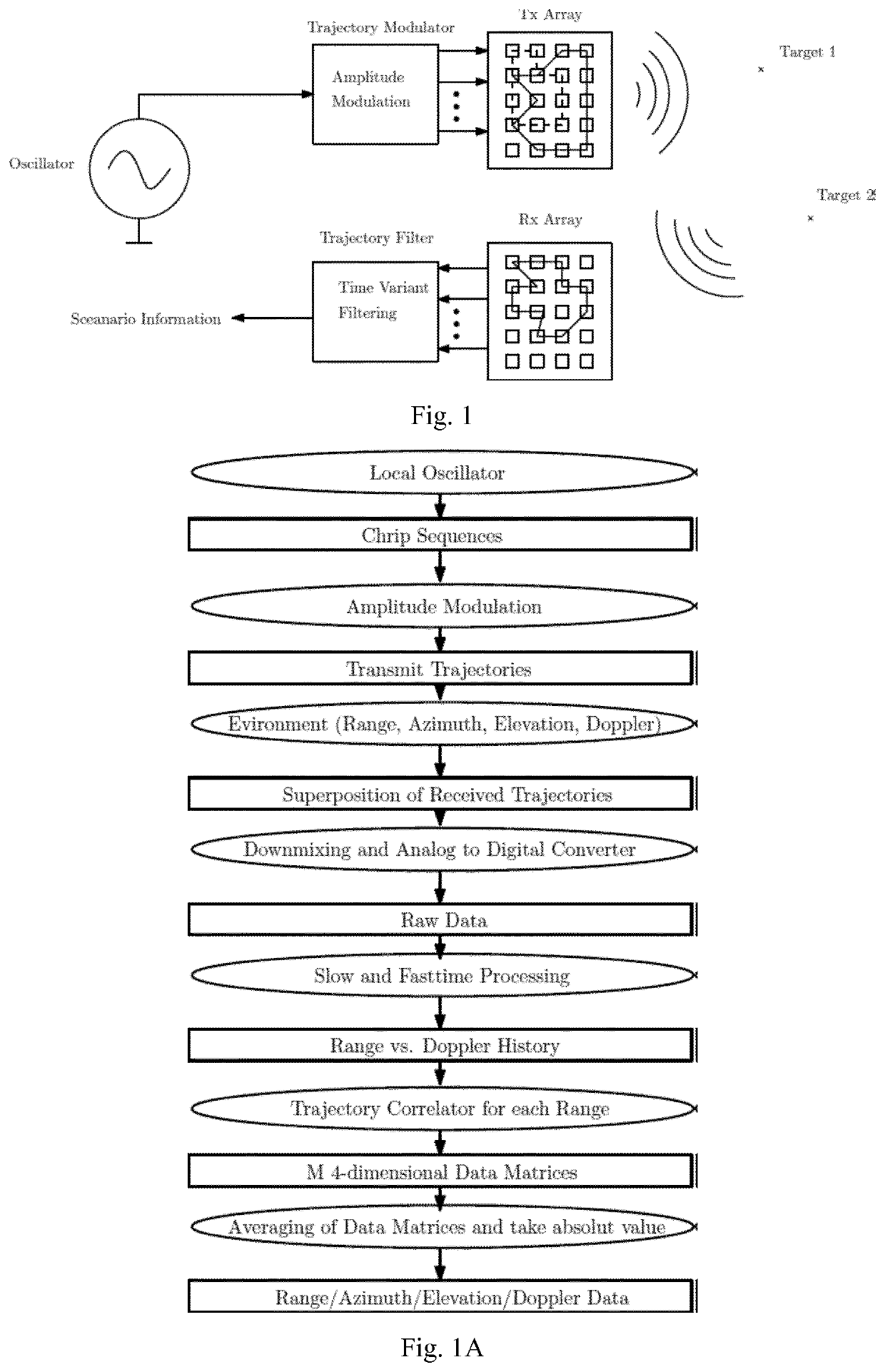
[0063]In order to achieve a nonlinear PCM, either the antenna elements are nonlinearly distributed and switched in equidistant time instances or the antenna elements are linearly distributed and the modulation scheme has be more advanced. Technically speaking, the switching is a binary amplitude modulation (AM). Therefore, a nonlinear PCM is a type of advanced AM. For a detailed investigation, a suitable signal model is used. As PCM can be seen as an AM and a FMCW scheme is used, the system model can be illustrated as in FIG. 1. It will be understood by the skilled person that the FMCW scheme is only used as an example and that the invention is not at all limited to FMCW.

[0064]The lines on the array illustrate the trajectories. As we will be seen, there is a transmit trajectory design and a receive trajectory design. The transmit trajectory design involves an AM and the recei...


PUM


Abstract

A method for obtaining an angle-Doppler signature for a target using sparse arrays in multiple-input-multiple-output (MIMO) radar, the MIMO radar including a transmit antenna array, the transmit antenna array being at least one-dimensional (e.g. 2-D, 3-D or 4-D) and having a plurality of antenna elements. The method includes generating transmit signals for transmission by the transmit antenna array, the transmit signals defining at least a first transmit trajectory (e.g. circular) of a phase center within the transmit antenna array, and transmitting the transmit signals using Amplitude Modulation on the transmit antenna array. The method further includes receiving receive signals from the target, the receive signals resulting from the incidence of the transmit signals upon the target, and determining the angle-Doppler signature from the receive signals. The first transmit trajectory is such that, in operation, the phase center undergoes non-linear motion within the transmit antenna array.

Description

TECHNICAL FIELD[0001]The present invention generally relates to a wireless detection of objects using MIMO radar, e.g. for use in an automotive vehicle, and more particularly to method and system for obtaining angle-Doppler signatures using non-linear phase center motion (PCM).BACKGROUND OF THE INVENTION[0002]In modern vehicles, radar systems are increasingly used, i.e. for sensing neighboring objects / targets (including other vehicles), for lane changing, collision avoidance and other driver assist functions.[0003]Unambiguous discrimination in radar systems with respect to angle, Doppler and range remains an area of investigation. Angular resolution is physically limited by the total antenna array size. The known virtual Multiple-Input-Multiple-Output (MIMO) concept provides better angular resolution with the same number of antenna elements with respect to their phased array counterpart. The utilization of sparse arrays and orthogonal signals leads to a virtually filled array in the...

Claims


Application Information

Patent Timeline
Patent Type & Authority Patents(United States)
IPC IPC(8): G01S13/34G01S13/42G01S13/87G01S13/931G01S13/93
CPCG01S13/42G01S13/931G01S13/878G01S13/343
Inventor HAMMES, CHRISTIANNIJSURE, YOGESHOTTERSTEN, BJORNSCHRODER, UDO
Owner UNIV DU LUXEMBOURG
Learn More