
Optical sensor device

Active Publication Date: 2020-09-08
AMS INT
View PDF9 Cites 0 Cited by
  • Summary
  • Abstract
  • Description
  • Claims
  • Application Information

AI Technical Summary

Benefits of technology

The patent describes two optical sensor structures that can detect the haze index of light in the visible range. These sensors have small sensor areas, making them suitable for outdoor use without saturating in direct sunlight. One sensor arrangement has two color filters of each color, but only one sensor without a color filter. This arrangement increases the dynamic range of the color sensor by making the sensor area smaller without a color filter. The optical sensor structures are shaped hexagonally and arranged in a honeycomb structure, which allows a close packing of the sensors. The sensor structures can be covered with an infrared-blocking filter for outdoor conditions. The patent emphasizes the importance of detecting the haze index from light in the visible range due to the scattering of ultraviolet and infrared light.

Problems solved by technology

However, on a cloudy day most of the light reaching the sensor is scattered and comes from different directions.
However, this arrangement with the diffuser and the air gap requires a certain package height of the sensor structure.
This means that the optical sensor has to be very sensitive to also detect the attenuated signal.

Method used


Image

  • Optical sensor device
  • Optical sensor device
  • Optical sensor device

Examples


Embodiment Construction

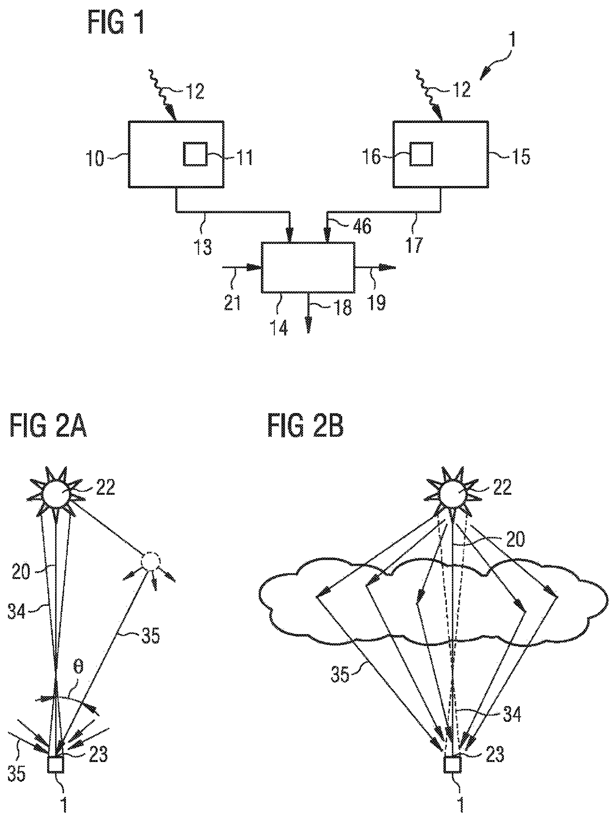
[0050]FIG. 1 shows an embodiment of an optical sensor device 1 that detects directional and non-directional light. A first optical sensor arrangement 10 includes at least one optical sensor structure 11. The first optical sensor arrangement 10 detects incident light 12. An output 13 of the first optical sensor arrangement 10 is connected to an evaluation circuit 14. A second optical sensor arrangement 15 includes at least one optical sensor structure 16. The second optical sensor arrangement 15 detects incident light 12. The second optical sensor arrangement 15 has an output 17 which is connected to the evaluation circuit 14 and provides an output signal 46. The evaluation circuit 14 has at least two outputs 18 and 19. The output 18 provides the output signal 46 of the second optical sensor arrangement 15. The first optical sensor arrangement 10 measures the incidence angle θ of incoming light 12 that is approximately on the main beam axis 20 of a light source 22. The output 19 of t...


PUM


Abstract

An optical sensor device comprises a first and a second optical sensor arrangement. In the first optical sensor arrangement at least one optical sensor structure measures the incidence angle of incoming light that is approximately on the main beam axis of a light source. The second optical sensor arrangement comprises at least one optical sensor structure with at least one optical sensor, at least two metal layers and opaque walls optically isolating the optical sensor. An evaluation circuit provides an output signal of the second optical sensor arrangement under the condition that the incidence angle measured by the first optical sensor arrangement lies within a set interval.

Description

BACKGROUND OF THE INVENTION[0001]The present application relates to an optical sensor device that can detect directional and non-directional light, for example ultra-violet light.[0002]Light reaching an optical sensor can be either direct, which means it comes directly from the light source and is not scattered, or it can be non-directional or ambient, which means that it is scattered. For the present application the light source can be, for example, the sun. Therefore, on a clear day with no clouds, nearly all of the light coming from the sun to the sensor is direct and not scattered. However, on a cloudy day most of the light reaching the sensor is scattered and comes from different directions. In order to measure the intensity of, for example, ultra-violet light, for different surrounding light conditions or different weather conditions it is necessary to detect light that comes from different directions.[0003]A known solution for detecting ultra-violet light is employing an inte...

Claims


Application Information

Patent Timeline
IPC IPC(8): G01J1/42G01J1/02G01S3/783G01S3/786G01J1/06
CPCG01J1/0266G01S3/783G01J1/429G01S3/7861G01J1/4204G01J1/42G01J1/06G01J2001/4266
Inventor MEHRL, DAVIDCHESLER, TROYDIERSCHKE, EUGENE G.
Owner AMS INT
Learn More