
Method for destruction of reducible contaminants in waste or ground water

a technology of reducible contaminants and waste water, applied in water/sewage treatment by ion exchange, water treatment parameter control, chemistry apparatus and processes, etc., to achieve the effect of easy and continuous automatic operation, no risk

Active Publication Date: 2020-08-25
BLUFLOW TECH
View PDF46 Cites 0 Cited by
  • Summary
  • Abstract
  • Description
  • Claims
  • Application Information

AI Technical Summary

Benefits of technology

[0015]These problems and others are addressed by the present invention, an exemplary embodiment of which comprises an apparatus that is configured to use a wide array of nanoparticles as adsorbent or absorbents. The apparatus allows for complete mixed contact with the aqueous solution being treated, allows for easy removal of the particles with no risk of the particles remaining in the purified water and provides for easy and continuous automated operation. The apparatus is also designed such that any level of purification of the water can be achieved including dissolved solids that are not collected by the particles but are still undesirable for using the water after removal of the target chemicals.
[0020]The disclosed subject matter presents several possible advantages. First, a wide variety of organic and inorganic materials can be destroyed. For instance, chlorinated hydrocarbons, metals and other contaminants can be chemically reduced to more benign forms. Only simple equipment is required and the method can be accomplished in a reasonable time period. The method is relatively inexpensive in relation to other comparable reduction methods. Powdered reagents can optionally be utilized. Another advantage is that the reaction conditions involved can be comparatively mild to other methods, such as hydrogenation with the use of gaseous hydrogen. Generally, the method performs admirably at relatively low pressures (below 100 psig (7.8 atm) and at ambient or slightly elevated temperatures.

Problems solved by technology

The apparatus is also designed such that any level of purification of the water can be achieved including dissolved solids that are not collected by the particles but are still undesirable for using the water after removal of the target chemicals.

Method used


Image

  • Method for destruction of reducible contaminants in waste or ground water
  • Method for destruction of reducible contaminants in waste or ground water
  • Method for destruction of reducible contaminants in waste or ground water

Examples


Embodiment Construction

[0032]The present invention now is described more fully hereinafter with reference to the accompanying drawings, in which embodiments of the invention are shown. This invention may, however, be embodied in many different forms and should not be construed as limited to the embodiments set forth herein; rather, these embodiments are provided so that this disclosure will be thorough and complete, and will fully convey the scope of the invention to those skilled in the art.

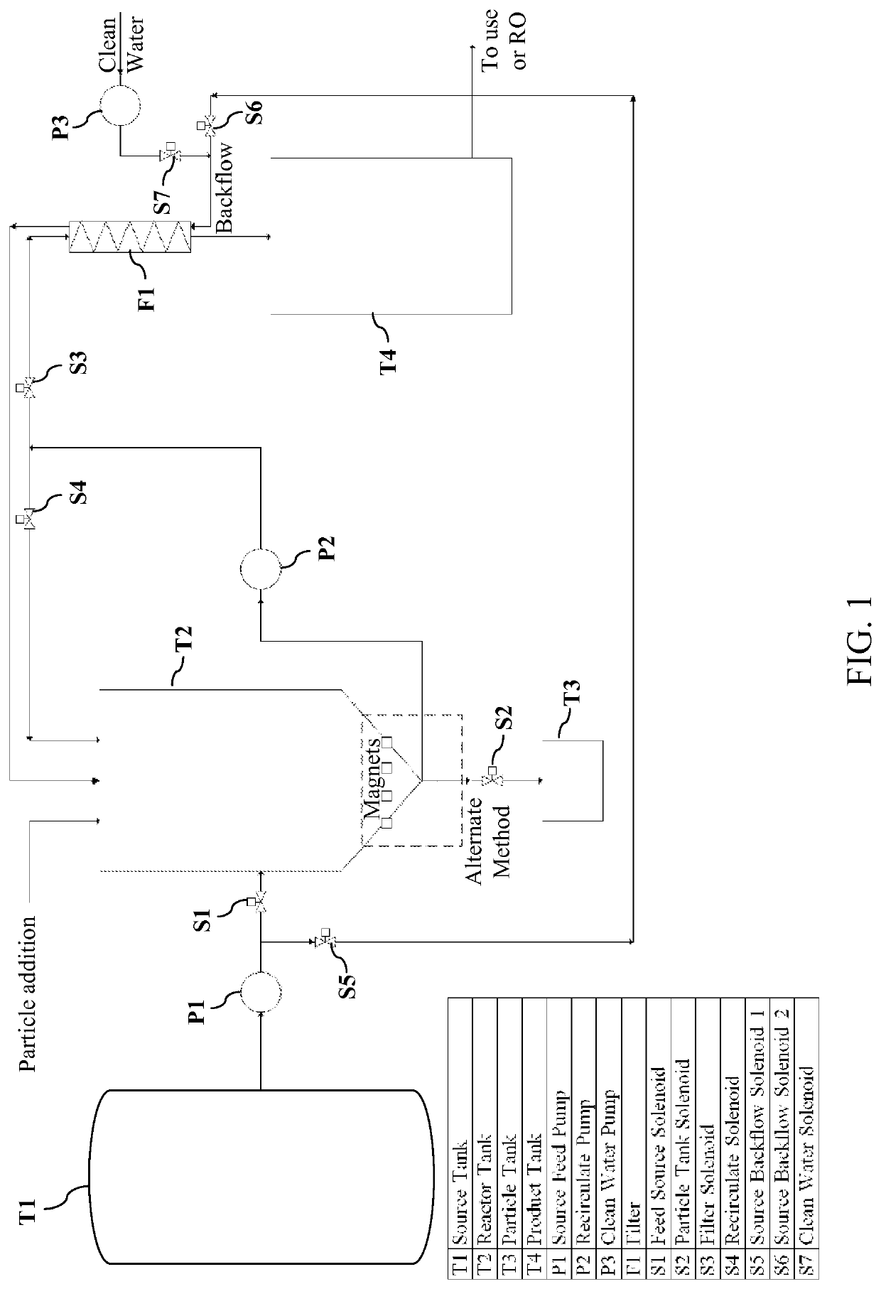
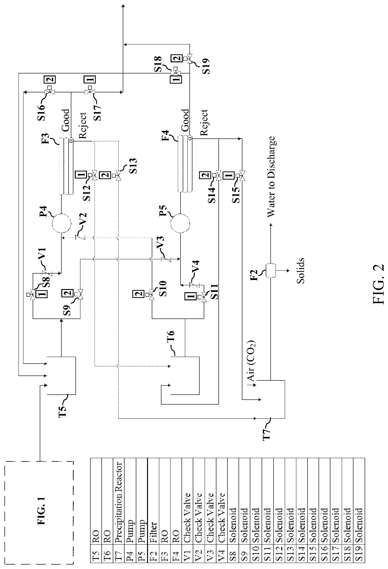
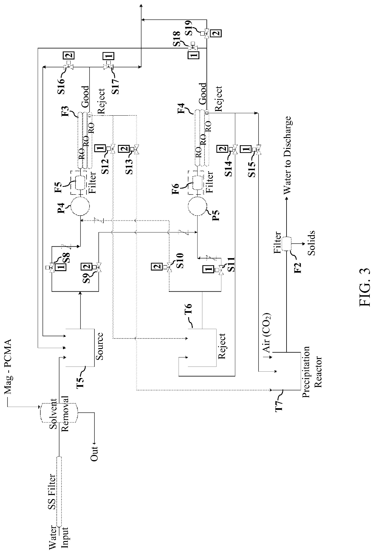
[0033]With reference to FIGS. 1-3, exemplary embodiments of a water purification apparatus configured to use a wide variety of colloidal particles and nanoparticles to remove chemicals from water with subsequent purification of the water beyond the chemicals removed, and method of water purification, will now be described.

[0034]FIG. 1 illustrates an example of part of an exemplary embodiment of the apparatus that relates to handling the particles and removal of the chemical of interest. FIGS. 2 and 3 illustrate exampl...


PUM

PropertyMeasurementUnit
sizeaaaaaaaaaa
surface areaaaaaaaaaaa
pressureaaaaaaaaaa

Abstract

A method of decreasing the concentration of certain contaminants in liquids by the chemical reduction of the contaminant using a hydride. A suitable reactor is charged with the contaminated liquid. An amount of catalyst and then an amount of hydride are added to the reactor. The hydride reacts with the contaminant in the liquid, chemically reducing and thus destroying a portion of the contaminant and thereby reducing the concentration of the contaminant in the liquid. Additional hydride can be added to further reduce the concentration to meet a desired level.

Description

CROSS REFERENCE TO RELATED APPLICATIONS[0001]This patent application is a continuation-in-part application of commonly owned U.S. patent application Ser. No. 13 / 764,760 entitled “APPARATUS FOR THE USE OF NANOPARTICLES IN REMOVING CHEMICALS FROM AQUEOUS SOLUTIONS WITH SUBSEQUENT WATER PURIFICATION” that was filed on Feb. 11, 2013. patent application Ser. No. 13 / 764,760 is incorporated by reference in its entirety herein. patent application Ser. No. 13 / 764,760 claimed priority under 35 U.S.C. § 119(e) of U.S. Provisional Patent Application No. 61 / 597,836, filed Feb. 12, 2012, entitled “APPARATUS FOR THE USE OF NANOPARTICLES IN REMOVING CHEMICALS FROM AQUEOUS SOLUTIONS WITH SUBSEQUENT WATER PURIFICATION,” the contents of which are incorporated herein by reference in their entirety.FIELD OF THE DISCLOSURE[0002]The present invention is directed to a water purification apparatus configured to use a wide variety of colloidal particles and nanoparticles to remove chemicals from water with s...

Claims


Application Information

Patent Timeline
Patent Type & Authority Patents(United States)
IPC IPC(8): C02F1/70C02F1/28C02F1/42C02F1/44C02F101/36
CPCC02F1/28C02F1/70C02F1/42C02F2209/006C02F1/705C02F1/444C02F2101/36
Inventor FARONE, WILLIAM A.PALMER, SHANE L.RIVERA, MIGUEL A.TAYLOR, CHRISTIANCHONG, DWAYNE
Owner BLUFLOW TECH
Learn More