
OLED panel temperature compensation system and OLED panel temperature compensation method

a technology of temperature compensation and oled panel, which is applied in the field of display, can solve the problems of large temperature difference and ineffective temperature compensation, and achieve the effect of accurately and effectively compensating the temperature of the oled panel

Active Publication Date: 2020-08-18
SHENZHEN CHINA STAR OPTOELECTRONICS SEMICON DISPLAY TECH CO LTD
View PDF8 Cites 1 Cited by
  • Summary
  • Abstract
  • Description
  • Claims
  • Application Information

AI Technical Summary

Benefits of technology

The present invention provides an OLED panel temperature compensation system and method that can accurately and effectively perform temperature compensation on the OLED panel. This system includes an OLED panel with a plurality of sub-pixels and a processing module connected to the OLED panel. The processing module receives and processes the initial data signals of the sub-pixels and the temperatures from the temperature sensors to obtain the to-be-displayed brightness and temperature of the sub-pixels, and generates and outputs compensation data signals corresponding to the sub-pixels according to the to-be-displayed brightness and temperature of the sub-pixels. This system and method allow for accurate and effective temperature compensation of the OLED panel.

Problems solved by technology

As the temperature difference is different in each region of the OLED panel due to heat dissipation and characteristics, the temperature difference is large and the temperature obtained by placing the temperature sensor on the PCB does not effectively compensate the temperature of the OLED panel.

Method used


Image

  • OLED panel temperature compensation system and OLED panel temperature compensation method
  • OLED panel temperature compensation system and OLED panel temperature compensation method
  • OLED panel temperature compensation system and OLED panel temperature compensation method

Examples


first embodiment

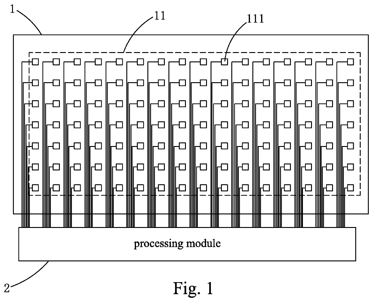
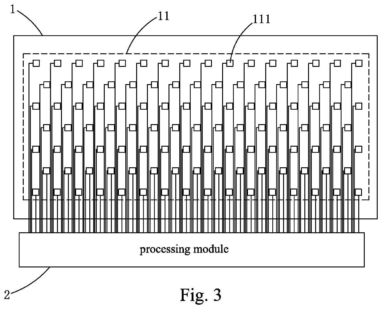
[0036]Refer to FIG. 1. The OLED panel temperature compensation system of the present invention comprises: an OLED panel 1 and a processing module electrically connected to the OLED panel 1.

[0037]The OLED panel 1 comprises a plurality of sub-pixels arranged in an array. One side of the OLED panel 1 is disposed with a temperature sensor layer 11. The temperature sensor layer 11 comprises a plurality of temperature sensors 111 disposed at intervals. Each temperature sensor 111 is electrically connected to the processing module 2.

[0038]The temperature sensor 111 is configured to detect the temperature at the location where the temperature sensor 111 is located and transmit to the processing module 2.

[0039]The processing module 2 is configured to receive an initial data signal of a plurality of sub-pixels and process to obtain a to-be-displayed brightness of the plurality of sub-pixels; the processing module 2 receives the temperatures from the plurality of temperature sensors and proces...

second embodiment

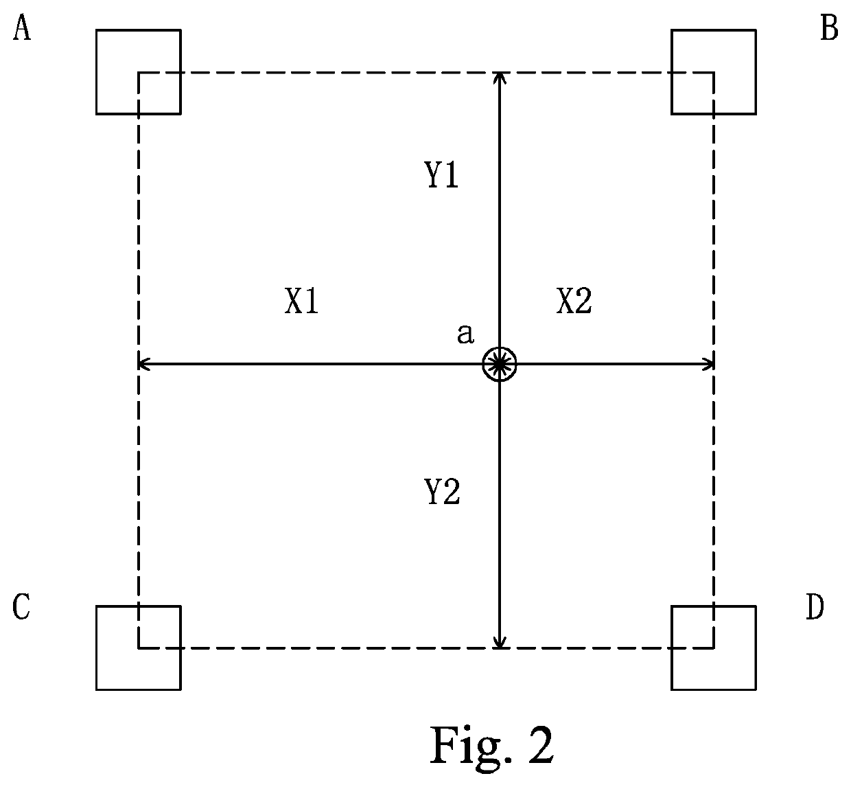
[0054]In the present invention, the bilinear interpolation calculation formula is as follows:

T′=[Y2′*(T1′*X2′+T2′*X1′)+Y1′*(T3′*X2′+T4′*X1′)] / [(X1′+X2′)*(Y1′+Y2′)];

[0055]wherein T′ is the temperature of the to-be-tested sub-pixel a′, T1′ is the temperature at the location of the first temperature sensor A′, T2′ is the temperature at the location of the second temperature sensor B′, and T3′ is the temperature at the location of the third temperature sense C′, T4′ is the temperature at the location of the fourth temperature sensor D′; X1′ is a distance between the line connecting the center of the first temperature sensor A′ and the center of the third temperature sensor C′ and center of the to-be-tested sub-pixel a′ in a direction parallel to the line connecting the center of the first temperature sensor A′ and the center of the second temperature center B′, X2′ is a distance between the line connecting the center of the second temperature sensor B′ and the center of the fourth tempe...


PUM

PropertyMeasurementUnit
distanceaaaaaaaaaa
threshold voltageaaaaaaaaaa

Abstract

The invention provides an OLED panel temperature compensation system and method. The system comprises an OLED panel and a processing module connected to the OLED panel, the OLED panel is disposed with a temperature sensor layer of a plurality of temperature sensors on one side or inside; when performing temperature compensation, the temperature sensor detects the temperature of the location and transmits to the processing module, the processing module receives and processes the initial data signals of the plurality of sub-pixels to obtain the to-be-displayed brightness of the plurality of sub-pixels, and receives and processes the temperatures from the plurality of temperature sensors to obtain the temperatures of the plurality of sub-pixels, and generates and outputs compensation data signals corresponding to the plurality of sub-pixels according to the to-be-displayed brightness and temperature of the plurality of sub-pixels. The OLED panel is thus accurately and effectively compensated for temperature.

Description

BACKGROUND OF THE INVENTION1. Field of the Invention[0001]The present invention relates to the field of display, and in particular to an organic light-emitting diode (OLED) panel temperature compensation system and OLED panel temperature compensation method.2. The Related Arts[0002]The organic light-emitting diode (OLED) display device provides the advantages of self-luminous, low driving voltage, high luminous efficiency, short response time, high definition and contrast, near 180° viewing angle, wide temperature range, and the ability to realize flexibility display and large-area full-color display, and is recognized by the industry as the most promising display device.[0003]According to the driving method, the OLED display device can be divided into two types: passive matrix OLED (PMOLED) and active matrix OLED (AMOLED), namely, direct addressing and thin film transistor (TFT) matrix addressing categories, wherein the AMOLED has the pixels arranged in an array, belongs to an acti...

Claims


Application Information

Patent Timeline
Patent Type & Authority Patents(United States)
IPC IPC(8): G09G3/3225G01K1/02
CPCG01K1/026G09G3/3225G09G2330/12G09G2320/041G09G3/3233G09G2300/0819G09G2320/029G09G2320/0295G09G2320/043
Inventor JIN, YUFENG
Owner SHENZHEN CHINA STAR OPTOELECTRONICS SEMICON DISPLAY TECH CO LTD
Learn More