Lighting device with wireless control element

a wireless control and lighting device technology, applied in the field of lighting devices, can solve the problems that the orientation may not meet certain desired specifications for the directivity of the antenna, and achieve the effects of improving the sensitivity or wireless range of the device, facilitating wireless control of the lighting device, and facilitating interfacing

Active Publication Date: 2020-08-18
SIGNIFY HLDG BV
View PDF21 Cites 0 Cited by
  • Summary
  • Abstract
  • Description
  • Claims
  • Application Information

AI Technical Summary

Benefits of technology

[0019]In this aspect, the antenna is separate from optical processing element and thus is more flexible in terms of its positioning and arrangement within the device. Since the antenna element is transparent for the light emitted by the plurality of light sources, the majority of light which falls incident upon it is transmitted across its body, rather than reflected or absorbed, meaning that any potential shadowing incurred by the element on the light output is mitigated in comparison with a standard opaque antenna element. In addition, where the device includes light sources of different colours, the transparent antenna lessens interference on the colour mixing of the different light, resulting in an improved colour performance in comparison with devices containing an opaque or near opaque antenna.
[0039]Provision of a control module allows the device to be operated in a standalone manner, i.e. without incorporation within a broader lighting system, where said broader lighting system may provide the control elements necessary to facilitate interfacing between the antenna element and the plurality of light sources.

Problems solved by technology

This imposed orientation may not meet certain desired specifications for the antenna directivity for achievement of optimal performance of the device.

Method used


Image

  • Lighting device with wireless control element
  • Lighting device with wireless control element
  • Lighting device with wireless control element

Examples


Embodiment Construction

[0067]It should be understood that the Figures are merely schematic and are not drawn to scale. It should also be understood that the same reference numerals are used throughout the Figures to indicate the same or similar parts.

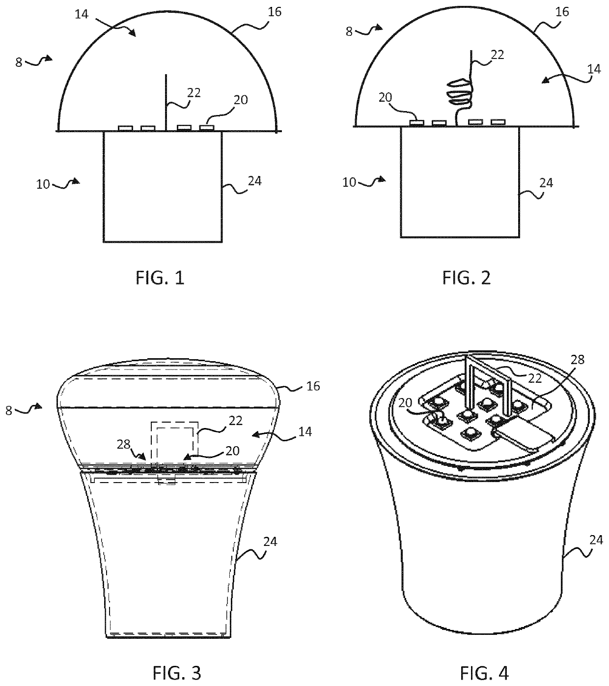
[0068]FIG. 1 schematically depicts a lighting device according to an embodiment. The lighting device comprises a first, upper module 8, the upper module comprising a light exit chamber 14 delimited by a curved light exit window 16, and a second, lower module 10, the second module mated with the first module to define the lighting device. Positioned within the light exit chamber are a plurality of light sources 20, the light sources mounted to a surface at the base of the chamber, and a translucent antenna element 22, the antenna element extending perpendicularly from said surface at the base of the chamber. Preferably the translucent antenna is as transparent as possible, in particular having a transmittance which is greater than or equal to 80%. The light so...


PUM


Abstract

The invention provides a lighting device, comprising a light exit chamber (14), delimited by a light exit body (16), a plurality of light sources (20), positioned within the light exit chamber (14), and arranged to emit light in the direction of the light exit body (16), an optical processing element, adapted to process the light emitted from the plurality of light sources (20), and a transparent antenna element (22), extending into the light exit chamber (14) and positioned relative to the plurality of light sources (20) such that each light source is arranged to transmit light toward the antenna element, wherein said transparent antenna element (22) is separate from the optical processing elements, wherein the transparent antenna element (22) being transparent for the light emitted by the plurality of light sources (20), and the antenna element (22) comprises: a transparent conductive material that is self-supporting.

Description

CROSS-REFERENCE TO PRIOR APPLICATIONS[0001]This application is the U.S. National Phase application under 35 U.S.C. § 371 of International Application No. PCT / EP2016 / 062870, filed on Jun. 7, 2016, which claims the benefit of European Patent Application No. 15192074.1, filed on Oct. 29, 2015 and Chinese Patent Application No. PCT / CN2015 / 083367, filed Jul. 6, 2015. These applications are hereby incorporated by reference herein.FIELD OF THE INVENTION[0002]The invention relates to a lighting device having wireless control functionality.BACKGROUND OF THE INVENTION[0003]With the ever increasing prevalence of wireless communication technology in aspects of the modern world, there has been a growing trend in recent years toward the implementation of wireless control (for example radio frequency control) within lighting systems. Wireless control of lighting affords users greater ease and flexibility in the operating of lamps and luminaires, rendering not only the standard operating processes ...

Claims


Application Information

Patent Timeline
Patent Type & Authority Patents(United States)
IPC IPC(8): F21V23/00H01Q9/42F21V3/02F21K9/232H01Q1/44F21V23/04H05B47/19H01Q5/22H01Q7/00F21Y115/10
CPCF21V23/003H01Q9/42H05B47/19H01Q5/22H01Q1/44F21K9/232F21V23/0435F21V3/02H01Q7/00F21Y2115/10F21S2/00F21V19/00F21V33/00H05B47/195
Inventor HE, YEMEIGU, WEIHUANG, MENGZHU, LIYIXU, YUNFEIQIAN, YIMENG
Owner SIGNIFY HLDG BV
Why Eureka
Try Eureka