System and method for measuring soil conductivity using existing farm implements

a technology of soil conductivity and system, applied in the direction of tilling equipment, instruments, spades, etc., can solve the problems of increased cost of extra pass through the field, bulky previous development devices, narrow window for making measurements, etc., and achieve the effect of low total investmen

Active Publication Date: 2020-08-04
VERIS TECH
View PDF72 Cites 1 Cited by
  • Summary
  • Abstract
  • Description
  • Claims
  • Application Information

AI Technical Summary

Benefits of technology

The invention is about a way to measure soil properties while driving around and getting a dense map of different properties with a low investment of time and money.

Problems solved by technology

However, previously developed devices are bulky and require mounting on a stand-alone implement frame.
The extra pass through the field is an added cost, and the seasonal window to make the measurements is narrow.
However, these moisture sensors do not capture the spatial variability as their expense and manual deployment make it unfeasible to collect enough measurements to produce a spatially accurate map of soil moisture.
However, the use of fixed moisture sensors does not link soil moisture with soil properties that affect water-holding capacity and crop usage of water.
However, it is not feasible to map soil pH or other chemical properties at a high density using conventionally collected lab samples, and the cost of a Veris on-the-go system for such mapping measurements is sometimes too expensive.

Method used


Image

  • System and method for measuring soil conductivity using existing farm implements
  • System and method for measuring soil conductivity using existing farm implements
  • System and method for measuring soil conductivity using existing farm implements

Examples


Embodiment Construction

[0038]A method and system for measuring multiple soil properties according to the present invention will now be described in detail with reference to FIGS. 1 to 19 of the accompanying drawings.

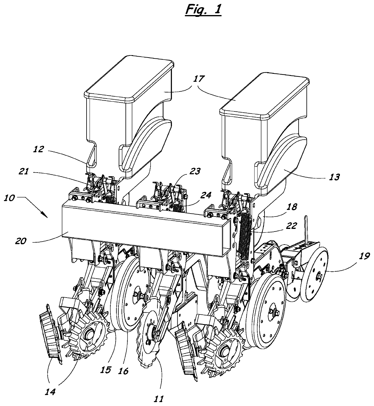
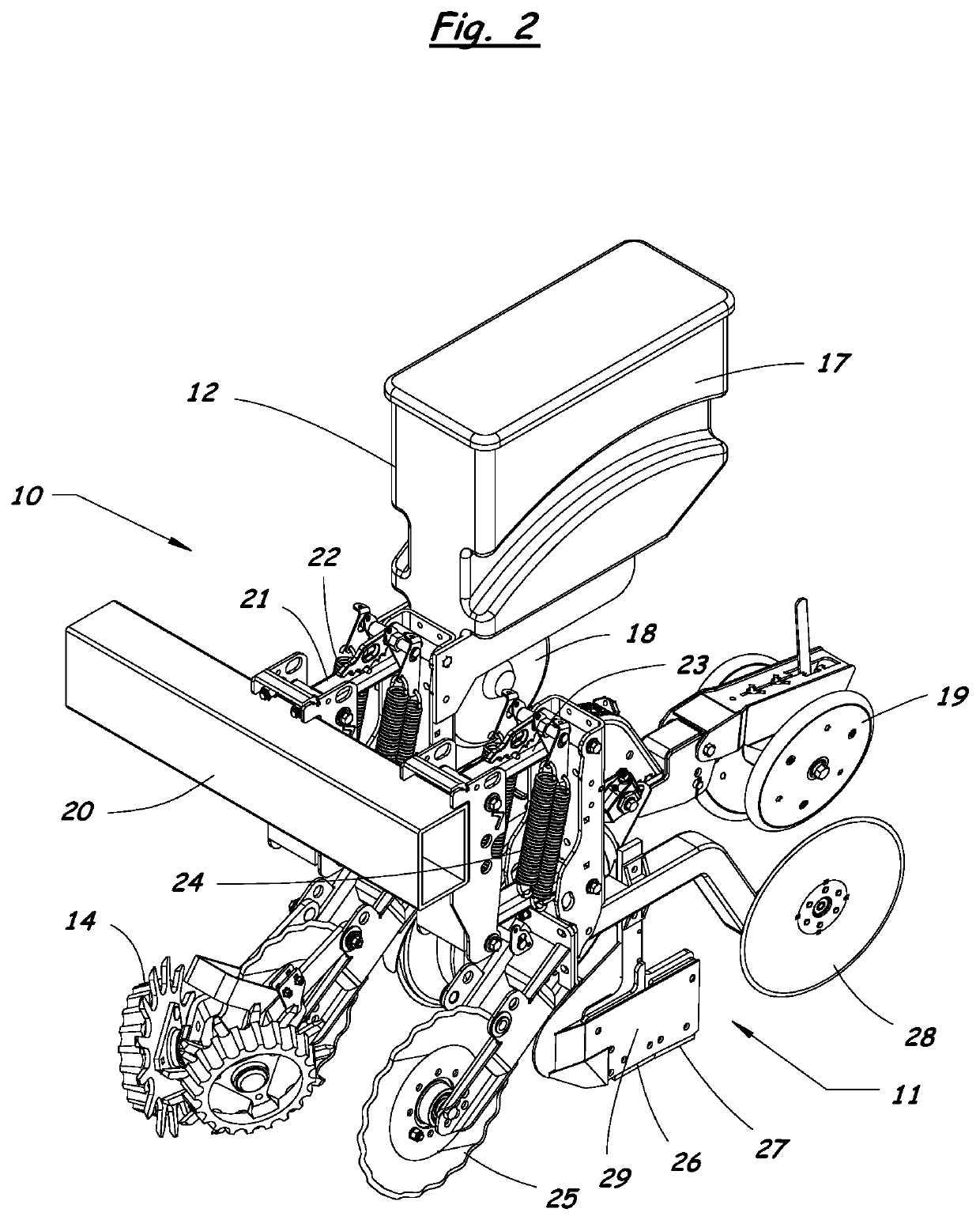
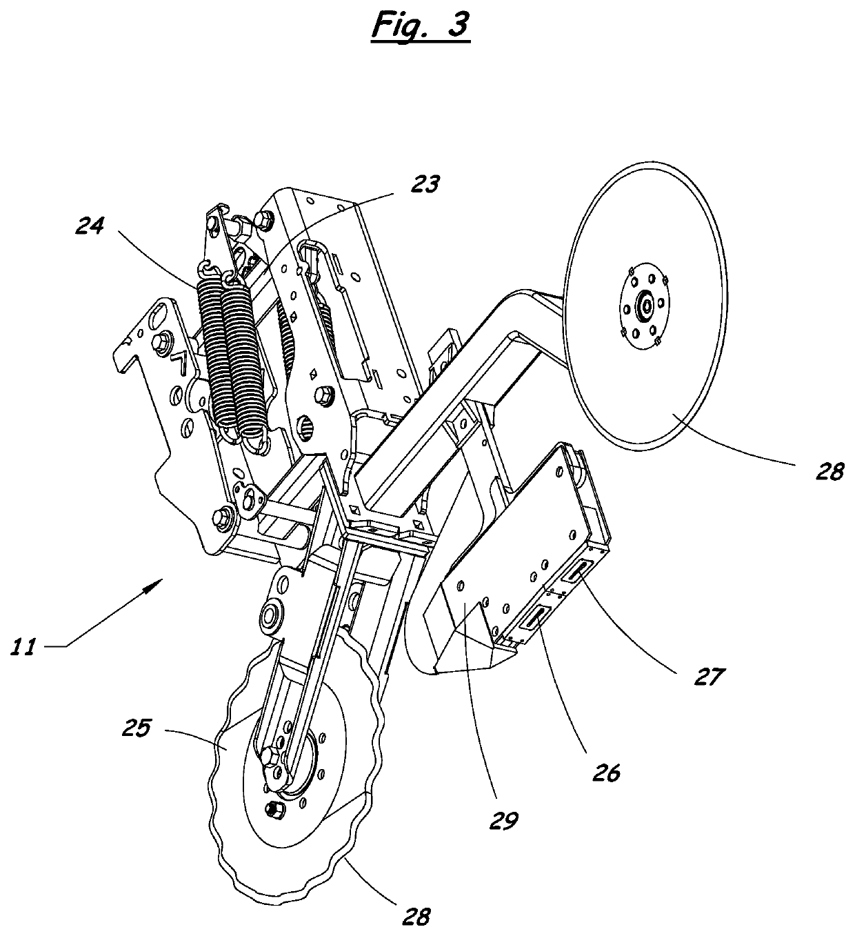
[0039]FIGS. 1 and 2 illustrate a row crop implement 10 equipped with a narrow profile sensor unit 11 according to the present invention. The narrow profile sensor unit 11 is positioned between two adjacent row units 12, 13 of the implement 10. The row units 12, 13 can be planter row units, as shown in FIGS. 1 and 2. Alternatively, the row units can be conventional strip tillage units or fertilizer applicator row units, which are attached to an implement tool bar.

[0040]The planter row units 12, 13 each have a row clearing assembly 14 for moving crop residue and debris to the sides of the row, a furrow opener assembly 15 with gauge wheels 16 for opening a furrow in the soil, a seed hopper 17, a seed metering mechanism 18 for dropping seeds through a seed tube into the furrow, and a furrow closin...


PUM


Abstract

A system for measuring soil properties on-the-go uses soil-engaging components of an existing farm implement as electrodes for a soil conductivity measurement system. The soil-engaging components can be: electrically isolated shanks and / or replaceable points or sweeps on a tillage implement; a row cleaner or coulter device on the front of a planter row unit, the closing wheels on the back of the planter row unit, or an entire planter row unit; or an additional soil contacting component added to an existing implement shank. A soil engaging component serving as an electrode is electrically isolated from other components of the implement. A soil conductivity measurement is made by passing current between a first pair of soil-engaging electrodes and measuring voltage resulting from the current between a second pair of soil-engaging electrodes. A narrow profile sensor unit can be attached to the implement to measure additional soil properties.

Description

RELATED APPLICATIONS[0001]This application claims the benefit of U.S. Provisional Patent Application No. 62 / 445,237 filed on Jan. 11, 2017. This application also relates to the subject matter of U.S. Provisional Patent Application Nos. 61 / 812,131 and 62 / 216,087, and U.S. Utility patent application Ser. Nos. 15 / 261,825, 14 / 253,304 and 14 / 253,839. The entire contents of these related applications are incorporated herein by reference.BACKGROUND OF THE INVENTIONField of the Invention[0002]The present invention relates generally to methods and systems for measuring and mapping soil properties across a field, and more particularly to a system and method for measuring soil properties on-the-go using existing farm implements.Description of the Related Art[0003]Soil texture and organic matter are major factors driving crop productivity. Prior art devices exist to measure these properties using electrical conductivity and optical sensing. For example, U.S. Pat. No. 5,841,282 issued to Christy...

Claims


Application Information

Patent Timeline
IPC IPC(8): A01B49/04A01B33/12A01G25/16A01B79/00A01C21/00G01N33/24
CPCA01B33/12A01G25/167G01N2033/245A01B79/005A01C21/007A01C5/062A01C21/00A01B47/00G01N33/245
Inventor LUND, ERICDRUMMOND, PAULJENSEN, KYLEMAXTON, CHASE
Owner VERIS TECH
Why Eureka
Try Eureka