Pressure sensor with reduced deviation of temperature distribution

a technology of temperature distribution and pressure sensor, which is applied in the field of pressure sensors, can solve the problems of reducing the uniformity of affecting the accuracy of the measurement, and the diaphragm may be subject to bending, so as to achieve the effect of increasing the temperature of the whole housing more uniformly, increasing the accuracy of the measurement, and reducing the deviation of the temperature distribution

Active Publication Date: 2020-07-21
HORIBA STEC CO LTD
View PDF12 Cites 0 Cited by
  • Summary
  • Abstract
  • Description
  • Claims
  • Application Information

AI Technical Summary

Benefits of technology

[0027]Thus, with the pressure sensor of the present invention, the thermal buffer member having the predetermined heat capacity is disposed on the inlet pipe. Therefore, even when the rapid temperature increase occurs in the fluid guiding pipe, it is possible to prevent a rapid temperature increase in the lower part of the housing and a local thermal expansion associated with the rapid temperature increase. Accordingly, the temperature of the whole housing can be increased more uniformly, namely, with less deviation of the temperature distribution. This makes it possible to reduce the difference in thermal expansion between the upper and lower parts of the housing, thereby ensuring that the diaphragm is less likely to bend in association with the rapid temperature change of the fluid guiding pipe.

Problems solved by technology

The diaphragm may be subjected to bending under stress due to the attached contaminant, thus causing a shift of an output signal of the sensor.
However, when the fluid guiding pipe is heated by the heater, the heat thereof is transferred to a lower part of the housing for the pressure sensor, and a rapid temperature increase occurs in the lower part of the housing.
This leads to a difference in thermal expansion between the upper and lower parts of the housing.
Consequently, the diaphragm supported (or joined) to the upper part of the housing may be subjected to bending, thereby lowering reliability of a measured pressure to be outputted from the pressure sensor.

Method used


Image

  • Pressure sensor with reduced deviation of temperature distribution
  • Pressure sensor with reduced deviation of temperature distribution
  • Pressure sensor with reduced deviation of temperature distribution

Examples


Embodiment Construction

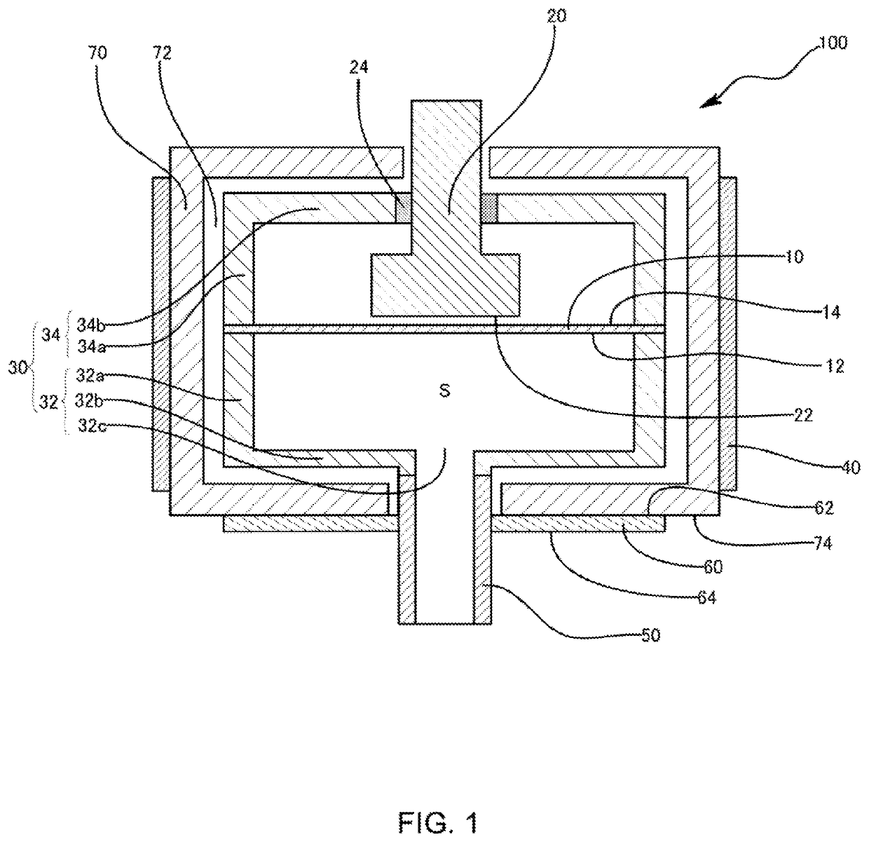
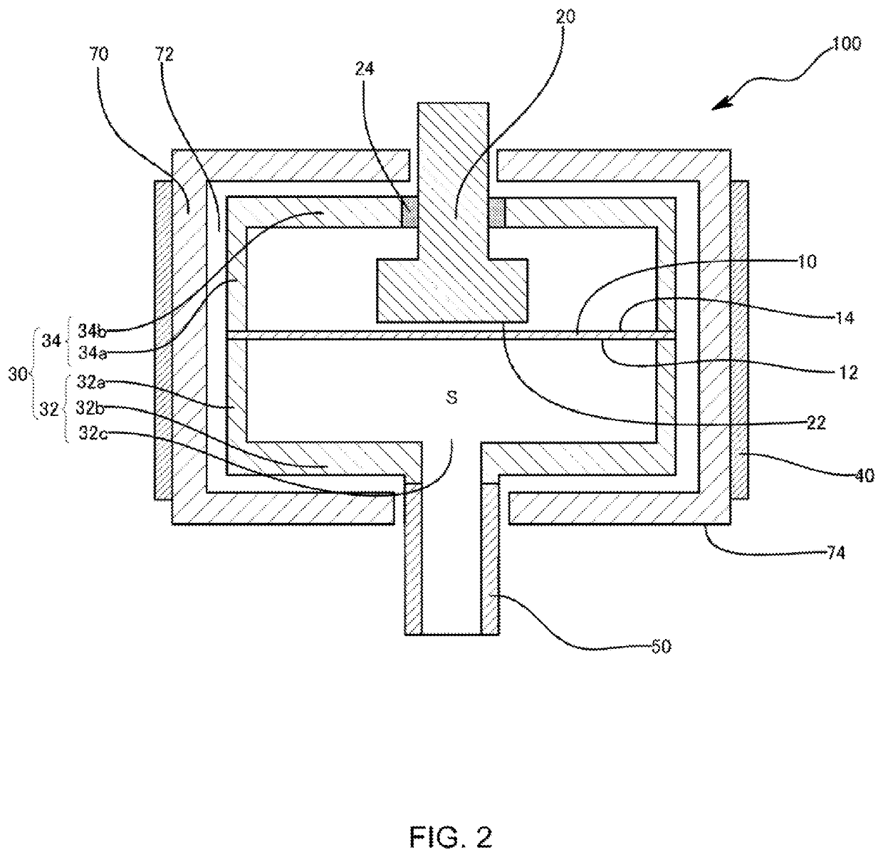
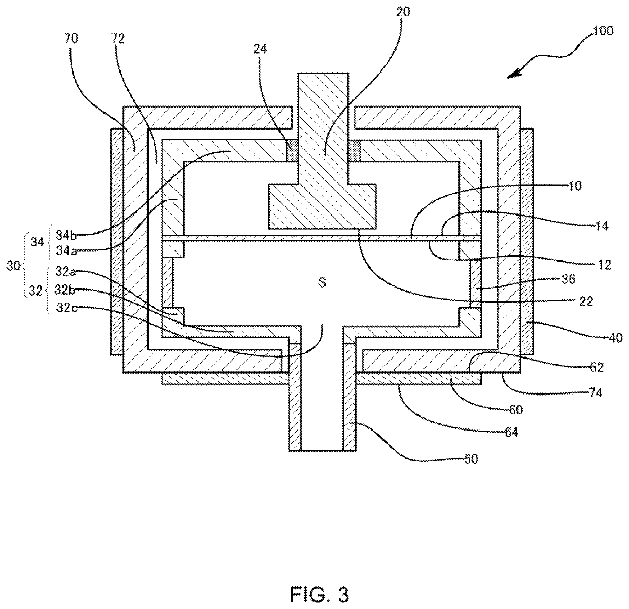
[0032]An embodiment of a pressure sensor according to the present invention is described below with reference to the drawings. The pressure sensor described below is intended to embody a technical idea of the present invention, and the present invention is not limited to the following embodiment unless otherwise noted. Contents described in the embodiment are applicable to other embodiments. In some cases dimensions members and their positional relationship illustrated in the drawings are magnified for the sake of clarity.

[0033]The pressure sensor 100 of the present embodiment is a capacitance diaphragm gauge corresponding to an absolute pressure measurement type of total pressure vacuum gauge. The pressure sensor 100 is configured to measure a pressure by detecting a displacement of capacitance between a diaphragm that displaces under pressure, and a fixed electrode, and then by converting the displacement to a pressure. A measured target fluid is guided into a measuring chamber S ...


PUM

PropertyMeasurementUnit
thicknessaaaaaaaaaa
thicknessaaaaaaaaaa
pressureaaaaaaaaaa

Abstract

The pressure sensor comprises the diaphragm, an electrode body, a housing, an inlet pipe, and a thermal buffer member. The diaphragm includes a pressure receiving surface configured to receive a pressure of a measured target fluid. The electrode body includes an electrode surface facing a rear surface of the pressure receiving surface with a gap interposed therebetween. The housing supports the diaphragm so as to form a measuring chamber by surrounding the pressure receiving surface. The inlet pipe is coupled to the housing and configured to guide the measured target fluid into the measuring chamber. The thermal buffer member is disposed on the inlet pipe and has a predetermined heat capacity. Accordingly, the diaphragm is unlikely to bend due to a rapid temperature change in a fluid guiding pipe disposed a fluid line.

Description

CROSS-REFERENCE TO RELATED APPLICATIONS[0001]This application claims priority on Japanese Patent Application No. 2017-065340 filed on Mar. 29, 2017, the disclosure of which is incorporated by reference herein.BACKGROUNDField[0002]The present invention relates to a pressure sensor for measuring a fluid pressure on the basis of a change in electrostatic capacity between a diaphragm that deforms under pressure and an electrode body.Description of the Related Art[0003]A pressure sensor has conventionally been used for measuring a pressure in a vacuum state during a thin film formation process in a semiconductor manufacturing step or the like. Examples of this type of pressure sensor include one which includes a housing 11 with an inlet part 10A for a measured target fluid, a diaphragm 32 that bends under a pressure of the measured target fluid guided through the inlet part 10A of the housing 11, and a sensor chip 30 that derives a change in the diaphragm 32 as a change in electrostatic ...

Claims


Application Information

Patent Timeline
Patent Type & Authority Patents(United States)
IPC IPC(8): G01L9/00G01L19/14G01L19/06
CPCG01L19/0627G01L19/147G01L9/0072G01L9/12G01L19/14
Inventor KISHIDA, SOTARONAKAI, JUNYAHATAITA, TAKEHISAKUWAHARA, AKIRA
Owner HORIBA STEC CO LTD
Why Eureka
Try Eureka