Voltage converter, electric drive system and method for reducing interference voltages

a voltage converter and electric drive technology, which is applied in the direction of power conversion systems, control systems, ac motor control, etc., can solve the problems of undesired interference current increase, disadvantage, and so as to minimize common-mode interference of inverters, the effect of reducing the cost of operation and maintenan

Active Publication Date: 2020-06-30
ROBERT BOSCH GMBH
View PDF10 Cites 1 Cited by
  • Summary
  • Abstract
  • Description
  • Claims
  • Application Information

AI Technical Summary

Benefits of technology

[0013]On the AC voltage side or motor side of the inverter, the filter consists of, in particular small, capacitors, in particular interference-suppression capacitors, which lead to a star point between the AC voltage conductors. Said star point is connected to the additional current conductor. Said additional current conductor carries the interference current whilst avoiding the disadvantages described in the introduction.
[0014]Advantageously, with this construction of the filter by means of the additional current conductor the filter effect of the DC-voltage-side capacitors, in particular x-capacitors, is combined with the AC-voltage-side filters, in particular on the motor side, of the inverter. The outlay for the required components can be minimized as a result. In particular, an x-interference suppression is also simultaneously provided with the center tap, such that a double implementation of the components is not necessary for this purpose.
[0017]The arrangement of an inductor on the input side of the inverter enables common-mode interference of the inverter to be minimized very well. Therefore, on the output side in the polyphase connection between inverter and load it is possible to dispense with an inductor, in particular a current-compensated inductor, which would involve a very high outlay on account of the higher number of phases between inverter and load. The voltage converter according to the invention thus enables a simple and cost-effective suppression of interference. By virtue of providing an additional current conductor, to which the first and second capacitors between the inductor and the DC voltage source and also the capacitors at the phase terminals of the inverter are connected on one side, the filtered interference is advantageously not conducted back to the structure (for example ground plate or vehicle structure) but rather on a separate path around the interference source (power electronics, in particular the inverter). That prevents the negative side effects described in the introduction. What is furthermore advantageous is that the three inserted capacitors at the three phases of the electric machine are no longer led toward the housing, or reference potential. A lower dielectric strength is sufficient as a result. Accordingly, the components can be chosen more favorably and in a smaller fashion and can also be embodied as ceramic component instead of film component.
[0018]In accordance with a further embodiment, a series circuit comprising the capacitor and an electrical resistor and / or inductance is arranged between the additional current conductor and each phase terminal of the inverter. Capacitor and resistor and / or inductance thus form an RC or RCL element. In this way, it is possible for the interference voltage spectrum emitted by the inverter to be damped in a targeted manner for a predefined frequency range. By introducing the electrical / ohmic resistors, it is possible to minimize the common-mode current that is coupled out.
[0019]In accordance with a further embodiment, the capacitor or the series circuit comprising the capacitor and electrical resistor and / or inductance is arranged together with the inverter in a common power module. The integration of inverter and capacitor or RC or RCL element in a common module enables a compact construction. Furthermore, a common cooling system can be provided for dissipating heat from the inverter and dissipating the electrical power loss of the RC or RCL element.

Problems solved by technology

Pulse-controlled inverters can cause common-mode interference in the event of a capacitive loading such as occurs, for example, as a result of stray capacitances in a connected electric machine.
As a result, the undesired interference currents are increased further.
This has a disadvantageous effect in terms of e.g. magnetic field emissions and interference voltages or currents on the HV-DC supply lines.

Method used


Image

  • Voltage converter, electric drive system and method for reducing interference voltages
  • Voltage converter, electric drive system and method for reducing interference voltages
  • Voltage converter, electric drive system and method for reducing interference voltages

Examples


Embodiment Construction

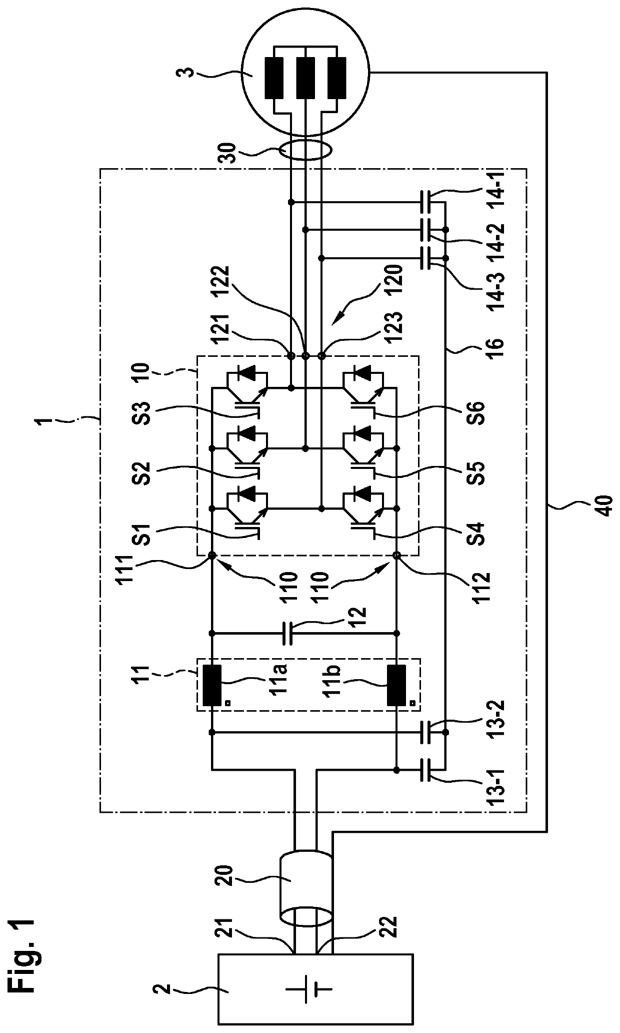
[0029]FIG. 1 shows a schematic illustration of an electric drive system in accordance with one embodiment. The electric drive system comprises a DC voltage source 2, an electrical load 3 and a voltage converter 1. Furthermore, the electric drive system can if appropriate, as necessary, also comprise further components. For the sake of providing a better understanding of the invention, however, possible further components of the electric drive system have not been illustrated here. The DC voltage source 2 can be a battery, for example. In particular, the traction battery of an electric vehicle is possible, for example, as the DC voltage source 2. Furthermore, arbitrary further DC voltage sources are possible, however, as the DC voltage source 2. The electrical load 3 can be, as illustrated here, a three-phase electric motor, for example. In this case, by way of example, arbitrary electric motors are possible as the electrical load 3. In particular, the electric motor 3 can be an asyn...


PUM


Abstract

The present invention relates to interference suppression of interference signals from an inverter. To this end, an inductor is provided at the input end of an inverter, in particular a pulse-controlled inverter. This inductor is preferably arranged between a DC voltage source and the inverter. Furthermore, two capacitors, one side of which is connected to an additional conductor, are provided between the inductor and the DC voltage source and further capacitors, one side of which is likewise connected to the additional conductor, are provided at the phase connections of the inverter.

Description

BACKGROUND OF THE INVENTION[0001]The present invention relates to a voltage converter and an electric drive system comprising a voltage converter and a method for reducing interference voltages. In particular, the present invention relates to the reduction of interference voltages from a voltage converter.[0002]The German patent application DE 41 07 391 A1 discloses an electric vehicle comprising a battery-fed inverter, in particular comprising a pulse-controlled inverter. A three-phase traction motor of an electric vehicle is fed in this case via an inverter. The inverter draws its energy from a battery.[0003]Pulse-controlled inverters can cause common-mode interference in the event of a capacitive loading such as occurs, for example, as a result of stray capacitances in a connected electric machine. In this case, it is desirable to reduce the interference voltage spectrum emitted in the environment of an electric machine in order for example to improve radio reception, in particul...

Claims


Application Information

Patent Timeline
Patent Type & Authority Patents(United States)
IPC IPC(8): H02M1/00H02P27/08H02M7/5387H02M1/12H02M7/483H02M7/00
CPCH02M7/003H02M1/126H02P27/08H02M7/483H02M7/5387H02M2001/009H02M2001/123H02M1/123H02M1/009
Inventor RASEK, GUIDO ALBERTBURGER, DENNIS
Owner ROBERT BOSCH GMBH
Why Eureka
Try Eureka