
Radiation detection device

a detection device and radiation technology, applied in the direction of measurement devices, radiation measurement, instruments, etc., can solve the problems of damage to electronic components, impact likely to be applied to portable electronic cassettes,

Active Publication Date: 2020-06-23
FUJIFILM CORP
View PDF11 Cites 0 Cited by
  • Summary
  • Abstract
  • Description
  • Claims
  • Application Information

AI Technical Summary

Benefits of technology

The invention aims to protect electronic components in a radiation detection device from impacts caused by falls. This is achieved by providing a device that can absorb the impact and prevent it from causing damage to the electronics.

Problems solved by technology

However, in a case in which the portable electronic cassette falls down, an impact is likely to be applied to the portable electronic cassette.
As a result, there is a concern that the electronic component will be damaged.

Method used


Image

  • Radiation detection device
  • Radiation detection device
  • Radiation detection device

Examples


Embodiment Construction

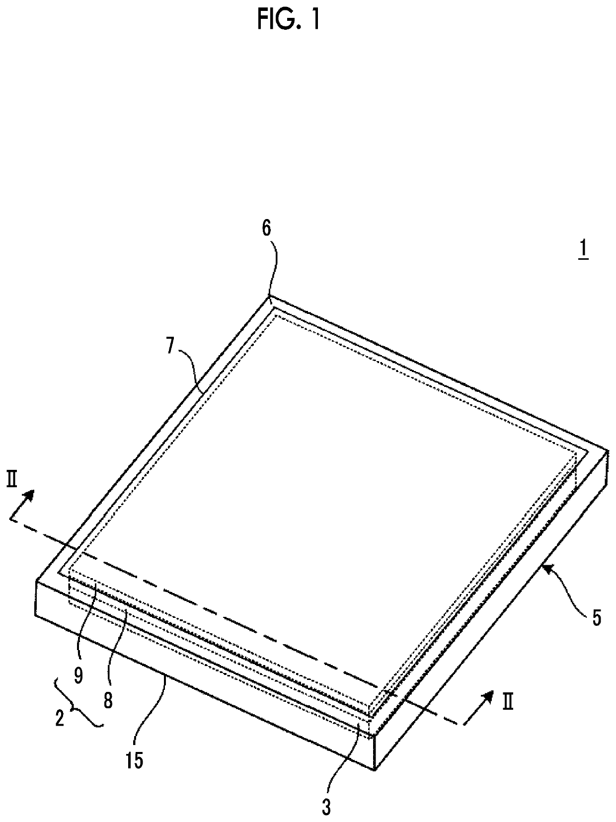
[0018]FIGS. 1 and 2 illustrate an example of a radiation detection device for describing an embodiment of the invention.

[0019]A radiation detection device 1 illustrated in FIGS. 1 and 2 is a so-called electronic cassette and comprises a radiation detection panel 2 that detects radiation, such as X-rays, a supporting member 3, and a housing 5 that accommodates the radiation detection panel 2 and the supporting member 3.

[0020]The housing 5 is formed in a rectangular parallelepiped shape and typically has a size based on the International Organization for Standardization (ISO) 4090:2001. It is preferable that the housing 5 is made of a material which can reduce weight and increase load resistance. Examples of the material include a magnesium alloy, an aluminum alloy, a fiber reinforced resin, a cellulose nanofiber (CNF) reinforced resin, and a resin that satisfy a specific gravity of 3.0 or less and a Young's modulus of 1.8 GPa or more. A rectangular opening is formed in a top plate 6 ...


PUM


Abstract

A radiation detection device includes: a radiation detection panel; a supporting member having a first surface and a second surface being opposite to the first surface, wherein the radiation detection panel is provided at a side of the first surface; an electronic component that is provided on the second surface of the supporting member and drives the radiation detection panel or processes an electric signal output from the radiation detection panel; and a housing that accommodates the radiation detection panel, the supporting member, and the electronic component, a bottom of the housing which faces the second surface comprises a flat portion and a slope portion that is adjacent to the flat portion and becomes closer to the second surface as becoming further away from the flat portion, and the electronic component is provided at a position as defined herein.

Description

CROSS-REFERENCE TO RELATED APPLICATIONS[0001]This application claims the benefit of Japanese Patent Application JP 2017-246639, filed Dec. 22, 2017, the entire content of which is hereby incorporated by reference, the same as if set forth at length.BACKGROUND OF THE INVENTION1. Field of the Invention[0002]The present invention relates to a radiation detection device.2. Description of the Related Art[0003]A so-called flat panel detector (FPD) is used to acquire a radiographic image of an object. The FPD comprises, for example, a scintillator that emits fluorescence corresponding to the amount of incident radiation and a detection substrate on which pixels detecting the fluorescence emitted from the scintillator are two-dimensionally arranged. Radiation transmitted through the object is incident on the scintillator and each pixel converts the fluorescence generated from the scintillator into an electric signal. Radiographic image data of the object is generated on the basis of the ele...

Claims


Application Information

Patent Timeline
Patent Type & Authority Patents(United States)
IPC IPC(8): G01T7/00G01T1/24G01T1/208G01T1/20
CPCG01T1/244G01T1/208G01T7/005G01T1/2018G01T1/2012G01T1/2006
Inventor HORIUCHI, HISATSUGUTATEISHI, MASATERUNOGUCHI, SHINSUKE
Owner FUJIFILM CORP
Learn More