
Sensor assembly

a technology of sensors and components, applied in the direction of coin-freed instruments, coin-freed apparatus details, instruments, etc., can solve the problems of false operation, insufficient strike of sensors, and misoperation of object-to-sensor strikes

Inactive Publication Date: 2011-07-26
HOMI IND
View PDF8 Cites 1 Cited by
  • Summary
  • Abstract
  • Description
  • Claims
  • Application Information

AI Technical Summary

Benefits of technology

The solution ensures accurate and reliable operation of the sensor by maintaining a consistent spatial position between the actuatable element and the sensor actuator, preventing false triggering and damage, and providing precise billing in vending machines.

Problems solved by technology

One problem with such sensors is that in real life there are many tolerances and inaccuracies during manufacturing and use that can result in malfunctioning of the object-to-sensor strike.
For example, the object may not strike the sensor enough to operate it, or worse, may not strike it at all.
Alternatively, the object may overstrike the sensor, that is, strike it too hard and cause damage thereto.
Alternatively, instead of the object striking the sensor, some other part may become misaligned and strike the sensor and cause false operation thereof.

Method used


Image

  • Sensor assembly
  • Sensor assembly
  • Sensor assembly

Examples


Embodiment Construction

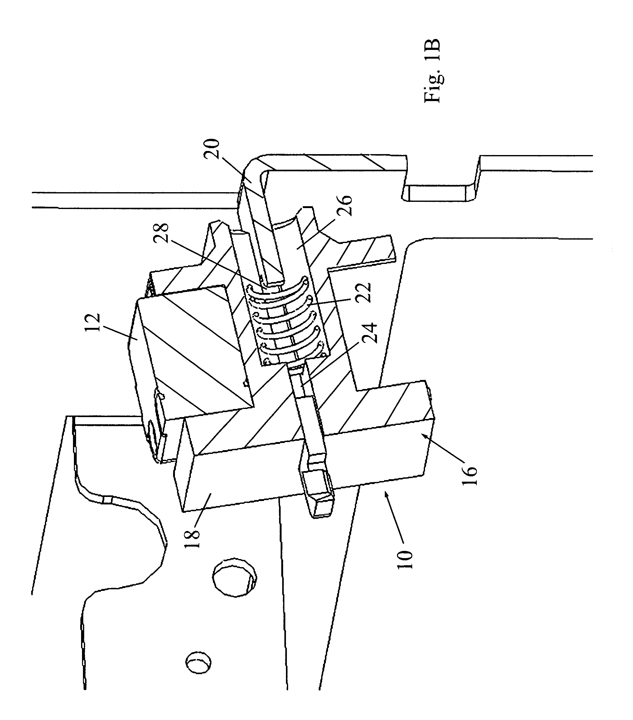
[0018]Reference is now made to FIGS. 1A-1B, which illustrate a sensor assembly 10, constructed and operative in accordance with a non-limiting embodiment of the present invention.

[0019]Sensor assembly 10 includes a sensor 12 that has an actuatable element 14. As will be described further below, actuatable element 14 is arranged to be actuated by a sensor actuator to cause an operation, such as a switching operation, and the actuatable element 14 must be substantially at a predetermined spatial position with respect to the sensor actuator in order for actuation to occur. The invention is described hereinbelow for the example of a microswitch and sensor 12 will alternatively be called microswitch 12. In the case of a microswitch, actuatable element 14 is a generic name for a button, lever, toggle or any other element that provides a switching operation when contacted with sufficient force, such as by pushing. However, it is understood that sensor 12 can be other sensors wherein the sp...


PUM


Abstract

A sensor assembly including a sensor including an actuatable element that causes an operation when actuated by a sensor actuator, the sensor including a holder, and a biasing device that imparts a biasing force against the holder that compensates for relative movement between the actuatable element and the sensor actuator so as to maintain the actuatable element substantially at a predetermined spatial position with respect to the sensor actuator.

Description

FIELD OF THE INVENTION[0001]The present invention relates generally to sensor assemblies, and particularly sensors actuated by an actuator, wherein the spatial position of the actuator is critical to the proper operation of the sensor, such as but not limited to, microswitches used in vending machines for detecting purchase of items.BACKGROUND OF THE INVENTION[0002]Sensor assemblies, particularly microswitch assemblies, are used to sense contact of different machine parts. For example, in vending machines for vending beverage cans and the like, a microswitch is used to detect when an item is purchased from the vending machine, so that the purchaser is billed properly for the item.[0003]These sensors thus rely on some actuator moving with respect to the sensor to cause operation of the sensor. In the case of a microswitch, for example, proper functioning of the sensor depends on some actuator striking a lever or button or some other mechanism on the microswitch. The object that strik...

Claims


Application Information

Patent Timeline
Patent Type & Authority Patents(United States)
IPC IPC(8): H01H9/02
CPCG07F9/026G07F11/72H01H3/166
Inventor ARTSIELY, EYAL
Owner HOMI IND
Learn More